• Hi Guest!
    If you appreciate British Car Forum and our 25 years of supporting British car enthusiasts with technical and anicdotal information, collected from our thousands of great members, please support us with a low-cost subscription. You can become a supporting member for less than the dues of most car clubs.

    There are some perks with a member upgrade!
    **Upgrade Now**
    (PS: Subscribers don't see this gawd-aweful banner
Tips
Tips

Copper Drain Lines for BJ8 Carb/Intake Manifold

Patrick67BJ8

Obi Wan
Silver
Country flag
Offline
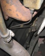
There are distinct "bends" in each of the two lines that come off the underside of the Intake manifold for a BJ8 and I need photo(s) showing those bent lines so I can replicate the bends. (I used to have a photo buy my dog ate it).
Thanks!
 
Hi Patrick, I do not have apicture .However, the drain lines have a somewhat lazy Z shape. The two bends are not sharp.
 
Keoke said:
Hi Patrick, I do not have apicture .However, the drain lines have a somewhat lazy Z shape. The two bends are not sharp.
I know about the Z but I'm trying to get a picture showing the Z for accuracy. Thanks!
 
andrea said:
have one photos of the correct overflow pipes on 100 6 or early 3000 (side shaft gearbox)
https://picasaweb.google.com/lh/photo/Md5eIdSo8ODEMy2NLFdlO9MTjNZETYmyPJy0liipFm0?feat=directlink
probably incorrect for BJ8.
I am very intrigued to see how the BMC was capable to change this good solution
Cheers
Andrea
You're right, not correct, but I hope someone will post a photo or send it to me and I'll post it. I guess they could have just ran the lines straight down like so many people do after a rebuild, etc., but they didn't. I wonder if there was a reason to make the "lazy Z's"?

I have seen a photo that was in black & white but I can't find it now. Thanks for posting the photo!
 
Patrick67BJ8 said:
andrea said:
have one photos of the correct overflow pipes on 100 6 or early 3000 (side shaft gearbox)
https://picasaweb.google.com/lh/photo/Md5eIdSo8ODEMy2NLFdlO9MTjNZETYmyPJy0liipFm0?feat=directlink
probably incorrect for BJ8.
I am very intrigued to see how the BMC was capable to change this good solution
Cheers
Andrea
You're right, not correct, but I hope someone will post a photo or send it to me and I'll post it. I guess they could have just ran the lines straight down like so many people do after a rebuild, etc., but they didn't. I wonder if there was a reason to make the "lazy Z's"?

I have seen a photo that was in black & white but I can't find it now. Thanks for posting the photo!
This must be the best kept secret or one of the most overlooked details in concourse quality restoration(s). No photos yet or even drawings.
 
Patrick67BJ8 said:
andrea said:
have one photos of the correct overflow pipes on 100 6 or early 3000 (side shaft gearbox)
https://picasaweb.google.com/lh/photo/Md5eIdSo8ODEMy2NLFdlO9MTjNZETYmyPJy0liipFm0?feat=directlink
probably incorrect for BJ8.
I am very intrigued to see how the BMC was capable to change this good solution
Cheers
Andrea
You're right, not correct, but I hope someone will post a photo or send it to me and I'll post it. I guess they could have just ran the lines straight down like so many people do after a rebuild, etc., but they didn't. I wonder if there was a reason to make the "lazy Z's"?

I have seen a photo that was in black & white but I can't find it now. Thanks for posting the photo!
HERE'S TWO PHOTOS.
I found my long lost photo and was sent one of an engine that Rich Chrysler did. Both are different and both appear to be BJ8 engines. I would think that the old dirty engine may be the most correct.
 

Attachments

  • 29961.jpg
    29961.jpg
    26.4 KB · Views: 601
  • 29962.jpg
    29962.jpg
    51.7 KB · Views: 579
I wonder if there was a reason to make the "lazy Z's"?


Yes: this was done to allow excess fuel to be expelled from the manifold while also assuring that excess air was not admitted which would complicate engine performance as well as carb tuning.---Keoke
 
Keoke said:
I wonder if there was a reason to make the "lazy Z's"?


Yes: this was done to allow excess fuel to be expelled from the manifold while also assuring that excess air was not admitted which would complicate engine performance as well as carb tuning.---Keoke
I know of owners who capped these holes off to plug up any air/vacuum leaks.
 
Patrick,

Below is a photo of what I have seen on several cars.

Duane
 

Attachments

  • 29965.jpg
    29965.jpg
    28.5 KB · Views: 558
Well that will handle the vacuum leak problem but most likely will complicate engine starting on cold mornings. Might also produce a continuous rich mixture.-Keoke
 
Duane_Rhynard said:
Patrick,

Below is a photo of what I have seen on several cars.

Duane
What series is this Healey? BJ7 or 8, etc. This complicates the issue because there appears to be three now, I know Rich was a stickler for details but the engine he did, that I have posted a photo of, I can't be sure what car it came out of.
Thanks,
For the photo!
 
Patrick,

I don't know what series the picture is, since it's not my car. I have personally seen this on several BT7's. The ones on my BN6 were missing, meaning plugged off.

I am probably going to look a "reported" unrestored phase 1 BJ8 on Monday, I'll have a look and see if the lines are there and take a photo.

Duane
 
How important is it that the two tubes be Z-shaped?
1. What effect would happen if the Z-shape is not correct?
2. What effect would happen if the tubes were straight?
 
Duane_Rhynard said:
Patrick,

I don't know what series the picture is, since it's not my car. I have personally seen this on several BT7's. The ones on my BN6 were missing, meaning plugged off.

I am probably going to look a "reported" unrestored phase 1 BJ8 on Monday, I'll have a look and see if the lines are there and take a photo.

Duane
We'll appreciate the photos or tell us which of these photos are correct for a BJ8.
Thanks!
 
AUSMHLY said:
How important is it that the two tubes be Z-shaped?
1. What effect would happen if the Z-shape is not correct?
2. What effect would happen if the tubes were straight?
Good questions. I don't have the answers and I can only assume that they were done certain ways for a reason other than looks. Maybe someone has technical details?
 
I could see them being in a "Z" shape to prevent air being drawn in, but the shapes shown so far don't do that; they would need to have a P-trap shape for that. The other reason I could see is that the tubes come quite long and it may be quicker (and, hence cheaper) to bend them rather than cut them off.

The tubes for BJ8 carbs are black plastic, BTW, after a short metal section. At least they were on the used carbs I bought.
 
John Turney said:
I could see them being in a "Z" shape to prevent air being drawn in, but the shapes shown so far don't do that; they would need to have a P-trap shape for that. The other reason I could see is that the tubes come quite long and it may be quicker (and, hence cheaper) to bend them rather than cut them off.

The tubes for BJ8 carbs are black plastic, BTW, after a short metal section. At least they were on the used carbs I bought.
The black plastic tubes are the ones for the carb overflow. The copper lines are located on the bottom both ends of the Intake Manifold.
 
Hi patrick, they did so in order to have both lines come together to fit in the clip that connects to the oil pan, plus I would guess they wanted to route the lines away from the exhaust as much as possible. I do remember my lines, that were original, did have two sharp 90 degree turns. The first turn was directly underneath the intake, the second to point down to exit through the clip. I'm sorry I don't have a photo but perhaps on the Moss catalog they do have a drawing showing the lines.
 
Back
Top