Hey Guest!


 Hey - did you know if you click on the title of a thread it will take you to the first unread post since you last visited that thread?
 but were afraid to ask:
  STOP!! Never post your email address in open forums. Bots can "harvest" your email! If you must share your email use a Private Message or use the
  smilie in place of the real @
 Pretty Please - add it to our Events forum(s) and add to the calendar! >>

Offline
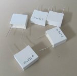
I have a good replacement capacitor for the unreliable ones that are currently being sold by the usual suspects. I got a few of them from Allied Electronics, https://www.alliedelec.com/. the part is Illinois Capacitor no. 224PPB102K, which has the allied stockno. 613-0592. There are others that should work; this one is overkill, for sure, but still is less than $3. And, it should last forever; no need to replace it periodically.
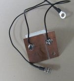
The first picture below shows them. they are a little large, about 1.25" x 1" x 0.5", and definitely won't fit inside the distributor. Even smaller capacitors, which might be OK, probably won't fit either. I mounted the cap on a piece of printed circuit board (second picture) so it could be mounted right on the coil (third pic.) This is a little clumsy, and not terribly attractive; for many of you that matters, so maybe a little more thinking about this is in order.
The next picture shows the test setup. I mounted a distributor in my little lathe, so I could spin it, and connected it all to a coil and spark plug. I powered it from a little power supply I have ($10 at the local electonics mart). It all worked well; I could see the plug sparking and the points as well. I was surprised at how little sparking there was at the points, but of course there can't be much or they wouldn't last. The main reason for all this was to monitor the waveform at the coil, so I could be sure it was doing the same thing that the standard system does. I had measured the waveform in the car before converting to the electronic ignition, and I was pleased, but not at all surprised, to see that it was virtually identical (last picture).
So, I think that this idea works, and certainly should be lot more reliable than those depressing caps I took apart.
If you want to try this yourself, and can't find the exact capacitor I used, you might look for a capacitor of 0.22 microfarads, at least 600 volts dc breakdown voltage. If you can find a "dv/dt" spec, multiply this (in volts per microsecond) by the capacitance in microfarads, which of course is 0.22. This should be at least 5 or 6. If the catalog doesn't have that spec, which it probably won't, use a fairly large, polypropylene film capacitor (like, 0.5" dia by ~1-1.5:" long). Something like this should be husky enough to handle the current. The PPA series, which Allied also has, should work fine (Allied part 613-0667). Don't use an electrolytic capacitor, or one of these teeny radio capacitors.
I'm still a little troubled by the need to mount this sensibly; I'm not sure what's the best, simplest way to do this. Most important is to strain-relieve the leads. Just soldering wires to the leads, and letting them flop in the breeze, probably will result in them breaking from fatigue before long. That's why I mounted the cap on the piece of board; I could put a dab of epoxy on the wires and they won't flex at the connection.
Remember also, the connections: one lead of the capacitor to the points (can be the points side of the coil, of course), the other to chassis ground. Don't forget to remove the original capacitor!