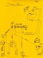
MaxWedge, I installed an alternator and then of course changed to negative ground when i retored my BJ7. I'm using the kit from Allen. The alternator is an AC Delco approx. mid '90s vintage. I believe it is a 65 amp alternator. My cut off switch is the original Healey unit mounted in the trunk in the original configuration. The only thing different back at the cut off switch is that I eliminated small white/black wire that runs from the cut off switch to the distributor. In the original design when the cut off switch is in the off position it also grounds this wire which grounds out the points so it can't start. I believe that is a bit of overkill since the cutoff switch eliminates power to the whole car when it is in the off position. So I eliminated this white/black wire. Some have said that it could be problematic and might ground the points while running some time, so I eliminated it.
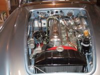
I eliminated my voltage regulator also and installed at that location a terminal bar to be able to make the necessary wire connections and changes. I will attach two pics. One is the engine bay and the other is the electrical plan layout. It's been working fine all summer. I call the terminal bar at the former regulator location the "Main Buss". You can see the large Red Wire on the alternator and it is going to the battery cable at the starter solenoid. This is the main charge wire to the battery. It is size # 10 AWG. You can see it running up along the original harness and going thru the firewall, that is because I ran it to an AMP meter before I brought it back out to go down to the solenoid. You can eliminate the AMP meter because in that configuration it will only read when charging anyway. The other smaller red wire on the alternator is seen there because that is the colour on the AC Delco plug the comes with the alternator. It is actually spliced to the yellow wire in the original wire harness that goes to the regulator location. It attaches to the smaller brown wire at the regulator location. It is the field excitor wire that gets the alternator to charge. The white wire at the alternator is spliced to the yellow/brown wire in the wiring harness which lead over to the regulator location as well, but it is just connected there to the wire that goes to the idiot light on the dash. That's why I call the terminal strip at the former regulator location the Main Buss because the wires at the alternator end up at the former regulator location and you have to connect them thru.
You can see in the engine bay pic that there is no fuse box on the fire wall. I didn't like the two fuse arrangement so I installed a new fuse box inside the passenger compartment up on the bulkhead above the clutch/brake/gas pedals. Each of the dark green wires that were on the fuse are now spliced to the lighter green wires (the closes colour I could get) and go inside the car to there own fuse. This fuse box is energized by the same wire that came from the ignition switch to feed the original fuse box. As such, I call this the "Ignition On Fuse Box " because it comes on with the ignition switch. I have installed another fuse box on the passengers side on the same bulkhead above the feet, which is on all the time. (except when the kill switch is turned off). This "Always On Fuse Box" is energized by the wire that fed the, ( i think is was the bottom original fuse ) larger of the two original fuses. This original fuse then also this fuse box feeds the horns, and all auxilary components such as, driving lights, radio, and now auxilary power ports for cell phones and ipads.
So this is how I handled installing an Alternator and upgrading to two modern fuse boxes. Maybe it will help you. Dave.

 Hey Guest!

 Hey - did you know if you click on the title of a thread it will take you to the first unread post since you last visited that thread?
 but were afraid to ask:
  STOP!! Never post your email address in open forums. Bots can "harvest" your email! If you must share your email use a Private Message or use the
  smilie in place of the real @
 Pretty Please - add it to our Events forum(s) and add to the calendar! >>