• Hey Guest!
    British Car Forum has been supporting enthusiasts for over 25 years by providing a great place to share our love for British cars. You can support our efforts by upgrading your membership for less than the dues of most car clubs. There are some perks with a member upgrade!

    **Upgrade Now**
    (PS: Upgraded members don't see this banner, nor will you see the Google ads that appear on the site.)
Tips
Tips

Cam degree wheel versus protractor

2wrench

Luke Skywalker
Country flag
Offline
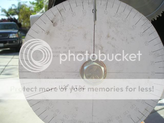
Check out this photo of a cam degree wheel. Calls a question.

P1010018-14.jpg


This is differet than the protractor-type I used to
degree my cam.

Therfore a quadruple-check. Does the following marking
on this protractor indicate 112 degrees ATDC (After top dead
Center). I have heard some conflicting opinions on what is
before top dead center and what is after. One more time.

Note my line drawn darker at what I think to be 112 after top
dead center. Thanks.

P1010010-21-1.jpg
 
This might help visulize it.
Hold your fan up to the crank. Consider the direction the fan would turn if the engine were running. Just imagine that one of the blades is at TDC. Given that, the marks where the fan would turn towards would then be before TDC and the marks where tha fan would be turning away from would be after TDC.

Since the cam turns the same direction the same applies to it.
 
So does this mean that as the crank turns clockwise,
that anything to the left of zero is after top dead
center? Is the marking I have drawn on this wheel showing
112 after top dead center?
 
Notice in the first pic, the "cam disk," that there is
a blue area that indicates: After top dead center. This
is to the right of zero.

This seems contrary to the greater percentage of
opinions I have heard and made me question. The
numbers on that wheel are way different than the
"protractor" type. I thought after top dead center was
to the left of zero. Youch.

Does it work to describe after or before as left or
right of zero?
 
The disc in the first picture seems to be showing the cam timings for a complete cycle, which (for a four stroke engine) is two rotations of the crankshaft. Maybe it is intended to show the cam timings to allow comparison between camshafts? I can't see any way you could easily attach that wheel to the crankshaft to measure the cam timing. In all the pictures I have seen showing someone timing a cam, the wheel in use is like the one you used, and that's what I used.

I am sure someone will come up with an explanation of what the coloured wheel is for, but if it turns out that the protractor you used isn't right then let me know - I need to get my engine crane unfolded...

Cheers
Alistair
 
How about this: Does my wheel marking correctly show
112 degress after top dead center? Yes or no?

The more confirmations, the greater my comfort level.
Thanks,
 
How about this: Does my wheel marking correctly show
112 degress after top dead center? Yes or no?

The more confirmations, the greater my comfort level.
Thanks,
 
These are the install instructions that came with my
cam:

BP270
-
TIMING VL/VC FL LTDC
HR270/2 INLET 22 - 70 .415"/.012" 112 .039
EXHAUST 62 - 28 .400"/.014" 106 .045
Latest design asymmetrical profile using short duration opening, long duration closing inlet with
long duration opening, short duration closing exhaust. Straightforward installation - no
machining required. Standard valve springs may be used. Up to 10 BHP can be gained with
excellent bottom end and mid range power.

INSTALLATION
To set your cam timing, you will need a 360 degree protractor and dial indicator. The engine
must be set to TDC and the protractor bolted to the crank pulley. Attach the dial indicator so that
the foot is resting on valve spring cap (or follower) Attach a pointer to engine and zero
protractor. Engine is now at top dead center with protractor reading zero.
Turn cam shaft until full lift is shown on the #1 intake valve. Then turn crank-shaft to 112
degrees ATDC. Next, without moving crankshaft or camshaft, install chain on crank sprocket
and line up the two closest holes on your cam sprocket.
NOTE
VL - Valve Lift
VC - Valve Clearance
FL - Full lift shown as degrees after TDC for inlet before TDC for exhaust.
LTDC - Lift at TDC
 
Just like everyone else says: Personally I think the problem stems from comparing apples and oranges.
The top picture is a degree wheel for the camshaft.
The bottom picture is a degree wheel for the crankshaft.

Usually we would use a crankshaft degree wheel and measure lift with a dial indicator.
 
Ayup. Put that pretty pink-n-blue one in a drawer someplace. Yes, the DKLawson wheel is marked for 112* ATDC... just be certain you have the index pointer well-and-truly indicating accurate TDC at 0* to begin with. Then turn the crank to the 112* point. Now rotate cam to achieve full lift at the tappet-lifter-follower thingie with the dial indicator as the tool. The lobe peak will have a "transition" window where it will travel a SMALL distance without the pointer moving... split that arc of movement in half to achieve the point of full lift. Easy-peasey!
 
Back
Top