• Hi Guest!
    You can help ensure that British Car Forum (BCF) continues to provide a great place to engage in the British car hobby! If you find BCF a beneficial community, please consider supporting our efforts with a subscription.

    There are some perks with a member upgrade!
    **Upgrade Now**
    (PS: Subscribers don't see this gawd-aweful banner
Tips
Tips

Bugeye generator/alternator conversion question

ichthos

Darth Vader
Country flag
Offline
I took the advice from some of you in an earlier post and purchased an alternator. I finally found one of the alternators that are housed in a C40 like body and still accepts the mechanical tach cable. It also comes with directions on how to wire it through the old voltage regulator. I have two questions: 1) On the old generator, there are two wires (F and D+) that only go one way since the posts are different sizes and the wires can only go on one way. On the new alternator however, even though it looks very close to a C40 generator, there are a few subtle differences. My directions show the two wires going to the back of the alternator in the same way, however the new alternator connections are different, with one in the back and another on the side near the back. How would I tell which is the F and which is the D+? 2) Also, the directions said to make sure that I have wire rated at 40 amp minimum-how do I know what the rating is? I am definitely no electrician, so any help would be greatly appreciated.
Kevin
 
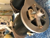
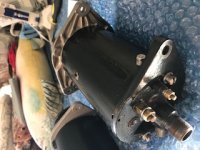
It would be very helpful if you post pictures of your new alternator.

I have not worked with any of the "Dynalite" type products as they have always been too expensive for me to consider. The following comments are "general".

The terminal lugs on the new alternator should still have different sizes. The larger lug should be for the output and will be on the rear housing. On most Dynalite type alternators I have seen the small lug for the field windings is also on the rear housing. If it's not... it could/would be the one on the side of the cylindrical body.

It will be difficult to have a single wire meet the vendor's 40 Amp current requirements. See the ampacity table in the link below:
Ampacity Table
You'll notice that according to the table, for modest/low temperature and a particular type of PVC insulation... you would need to use 8 AWG cable on a single, large, female spade lug. 8 AWG is fairly large and will certainly look out of place.

On traditional alternator conversions people typically use (2) lengths of 10 AWG wire. One goes from the first large spade lug on the alternator to the modified car wiring, the second wire goes from the second large male lug on the alternator to the hot junction on the starter solenoid. However, your Dynalite type alternator probably only has one large male spade lug.

I would contact the folks at Britishwiring.com and ask them what they have to offer for connectors that might allow you to crimp two 10 AWG wires into a large female spade terminal. If they don't have a single terminal to accept two wires, perhaps they have a piggyback terminal that will allow two connections.
 
IMG_5576[134].jpg
 
The male spade terminals still look to be different sizes with the smaller being on the cylindrical housing as I suggested above.

When I looked up C40 terminals I found that on the Auto Electric Supplies website that the larger 3/8" terminal is D+ and the smaler 1/4" terminal is F See the page linked below but notice this page is for a sealed, traditional, dynamo, not an alternator.
https://www.autoelectricsupplies.co.uk/product/891
 
Thanks Doug. It makes sense that the heavier terminal on the back would be the postive, but I was not sure. I was disappointed by the spade connections. I want to keep the original eye type fittings in case I need to go back for some reason. Can anyone suggest a way to do this?
 
I have never worked on a Bugeye. Can you post a picture of the original dynamo and the harness terminals that connect to it?
 
I don't remember seeing what ground your car is. Is it positive or negative ground?

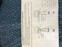
I cannot read the instructions you posted since the image is quite small. Can you compare the wiring your vendor shows to that shown in the links below? Do any of the wiring schemes shown match what your instructions show?
http://www.racemettleltd.co.uk/fitalt.html
and
http://www.wosperformance.co.uk/products/dynators/fitting-instructions/negative-earth-systems/

For the field winding connections (F) it looks like you might be able to just remove the nut and spade terminal on the new alternator and connect your ring terminal there. I am not sure what the best solution is for the D+ connection. I will give this some thought.
 
Back
Top