• Hi Guest!
    You can help ensure that British Car Forum (BCF) continues to provide a great place to engage in the British car hobby! If you find BCF a beneficial community, please consider supporting our efforts with a subscription.

    There are some perks with a member upgrade!
    **Upgrade Now**
    (PS: Subscribers don't see this gawd-aweful banner
Tips
Tips

BN6: Shock absorbers do not fit after renewing the link arms

BN6_2197

Jedi Trainee
Country flag
Offline
Gents,

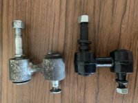
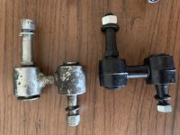
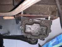
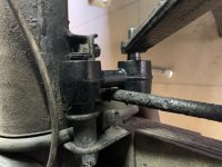
after renewing the link arms, the shock absorbers do not fit to the frame anymore. With the old ones everything is fine. Any ideas?

You can find pictures of the problem as well as the old and new link arms attached.

Cheers,

Volker
 

Attachments

  • IMG_0408.jpg
    IMG_0408.jpg
    64.7 KB · Views: 207
  • IMG_0407.jpg
    IMG_0407.jpg
    66.5 KB · Views: 192
  • IMG_0469.jpg
    IMG_0469.jpg
    68.5 KB · Views: 193
What do you mean by 'renew?' The 'old' and 'new' links look to me to be completely different; i.e. the old are cylindrical, and the new are barrel-shaped, and appear to have welded seams. Also, from measuring my screen with a tape measure the new appear to be about a quarter inch longer socket-to-socket (that could cause the cocking of the shock body.

Do you mean replaced, by chance?
 
It looks like the center-to-center dimension of the new link is greater than the old one. Measure them to confirm.

Bob was quicker than I was.🙂
 
Last edited:
I agree with Bob & Jack on center-to-center dimensions, they do not look the same in the pictures anyway.

It also looks to me like the diameter of the tapered pin on the black ones may be a fatter taper which would alter the depth of insertion into the shock arm?

Dave
 
The studs are painted - those on the links. The unpainted others in picture 3 are bolts.

IMO, the fact that the taper doesn't seat as far as the original is probably the problem. The link being a little longer just positions the shock arm at a slightly different vertical position.

I'd remove the paint from the tapers, then measure the min & max diameters, comparing to those of the originals.
 
As steveg said, the gap is larger with the new link arms. Do I have the correct shock absorbers for the BN6? I have Armstrong Part No 5550*2 and 5550*3 (see picture attached).
 
Gents, can anybody tell me if this is the correct positioning of the uppet stud of the link arm? Or must the mount of the leaf spring contact the nut of the link arm?

What is the way to bring the link arm in the right position at the mount of the leaf spring? Ca I use a hammer?

Cheers,

VolkerIMG_0595.jpg
 
Volker,

There should be a distance tube, Moss#725-130, between the two ears on the axle. The upper stud goes through it. Tightening the nut while holding the hex section on the stud should pull the stud into place.
 
Gents, after cleaning off the paint and tightening the nut of the upper stud very hard, I was able to bring the link arm into the right position at the leaf spring. Unfortunately after adding the shock absorber I face the same problem as with the old link arm: the upper stud was squeezed out to the right of the upper cylinder of the link arm :-( Actually this was the reason why I started to replace it.

Is this expected or at least"ok"? Please note tghe distance of the lower cylinder of the link arm and the lever of the shock absorber.

Volker


IMG_0703.jpg IMG_0692.jpg
 

Attachments

  • IMG_0692.jpg
    IMG_0692.jpg
    73.4 KB · Views: 134
Not wishing to complicate things, but since it hasn't been mentioned...

The stud going through the axle (with the distance tube) and for that matter, the tapered stud going into the shock arm, should not be tightened down until the weight of the car is resting on the wheels (in other words, sitting at normal ride height) or the rubber bushing longevity will be compromised.

A rubber bush does not rotate as the body of the car moves up and down over road bumps, it flexes, or twists. If you tighten those links down when the wheels are off the ground, the rubber bush will already have some of its twist being used. When the car goes over a bump and the suspension is fully compressed, the bushing may be twisted beyond its engineered range of flexing.

On the other hand, if you enjoy doing the job(s) often, don't worry about it... :devilgrin:
 
Gents, after cleaning off the paint and tightening the nut of the upper stud very hard, I was able to bring the link arm into the right position at the leaf spring. Unfortunately after adding the shock absorber I face the same problem as with the old link arm: the upper stud was squeezed out to the right of the upper cylinder of the link arm :-( Actually this was the reason why I started to replace it.

Is this expected or at least"ok"? Please note tghe distance of the lower cylinder of the link arm and the lever of the shock absorber.

Volker


View attachment 62947 View attachment 62948


Does anybody have an answer or meaning to my „distance“ problem?

Randy, thanks for this valuable hint :encouragement:

Volker
 
Last edited:
Gents, after cleaning off the paint and tightening the nut of the upper stud very hard, I was able to bring the link arm into the right position at the leaf spring. Unfortunately after adding the shock absorber I face the same problem as with the old link arm: the upper stud was squeezed out to the right of the upper cylinder of the link arm :-( Actually this was the reason why I started to replace it.

Is this expected or at least"ok"? Please note tghe distance of the lower cylinder of the link arm and the lever of the shock absorber.

Volker


View attachment 62947 View attachment 62948

A) Is the replacement from one of the regular suppliers - AHspares for instance? If so, maybe that's the only one available out there. If not, suggest returning it and sourcing a good one - as it clearly doesn't fit properly.

Can't tell from the pic if the tapered stud is seated in the shock arm and can be bolted up solidly with the shock bolted to the chassis.

B) If A) is not an option and everything bolts up solidly - with the car on the ground per Randy above - it should work.
 
I still think the taper on the link pin doesn't look right but that could just be the picture.

One way to check the stress level on the link is to install the link in the axle bracket and the shock arm (not completely tight as Randy suggested, but snug enough to make sure it's roughly where it will be when fully tightened) while the shock body is loose/unbolted. The shock should sit in it's normal location when the link is connected... ie, there should be no strain sideways on the link in order to tighten the shock mounting bolts. If there is any sideways strain, the rubber in the links will not last long.

Dave
 
Back
Top