• Hi Guest!
    You can help ensure that British Car Forum (BCF) continues to provide a great place to engage in the British car hobby! If you find BCF a beneficial community, please consider supporting our efforts with a subscription.

    There are some perks with a member upgrade!
    **Upgrade Now**
    (PS: Subscribers don't see this gawd-aweful banner
Tips
Tips

BJ7 wiring power path

RestoreThemAll

Jedi Warrior
Country flag
Offline
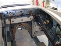
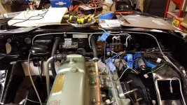
I'm not great with wiring. Can someone verify that I have the power path correct on my BJ7?

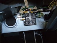
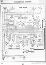
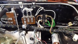
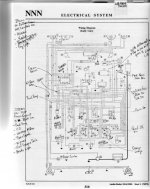
1) A wire from the starter solenoid goes to the control box A connection on its way to the 50 amp fuse.

2) There is continuity between the A connection and the A1 connection on the control box. From the control box A1 a line goes to the light switch then the ignition switch.

3) Turn the key; from ignition switch to coil then fuse box 35 amp fuse (on the diagram)...Ignition switch to fuse box and a separate line to coil (both old and new wiring harnesses). No real difference between these two paths, diagram vs wire, correct?

When the key is turned the 35 amp fuse is hot. The OD relay and fuel pump are also hot before the fuse.
 

Attachments

  • Wiring Diagram FOR BJ7 with labels.pdf
    287.3 KB · Views: 250
Thank you CraigC.

Bob, a new wiring harness is completely installed. I've looked at different methods to add fuses. I'll probably go with one or two Triumph TR6 Lucas boxes. They have four fuses each. I may add an in line fuse or two in addition to or in place of one of the boxes. The TR6 box isn't AH but it is period correct. I just don't like the look of modern options. What were you thinking?

Dale
 
Dale, when it comes to adding fuses I thought I would give you at least one idea. I'm not familiar with the TR fuse boxes so I might be duplicating what you are thinking of. In my opinion you can put a six position fuse box in the same place as the original box but you'll have to be very specific where you place it because the wires at the location are very short. All the green wires on the driver's side of the existing fuse box can be put on their own respective fuse if you position the box just right. There should be 5 of the green wires there. The one or two other wires that are on the top fuse cannot be put on the same fuse box because these wires on the top fuse are supplied from the "A" terminal of the voltage regulator while the 5 lower green wires are supplied thru the ignition switch. That is why I elected to put in two fuse boxes. the one box with the 5 green wires is hot with the ignition on, and the other fuse box is hot all the time. Of course in putting in 2 fuse boxes I had to move them inside. You can see from my pic where I spliced the green wires out to make them longer then routed them inside. Your dash lights are powered directly from the headlight switch and originally are unfused. Since the headlight switch is ahead of the ignition switch the best way to fuse these dash lights is to install an in line fuse holder from the terminal on the headlight switch that supplies the dash lights. You'll notice that the headlight switch and this then being the headlights are supplied directly from the A1 terminal of the voltage regulator and are unfused. This is the way it should be as you will find that most early cars before & after the war did not fuse their headlights. It had been thought that is was better to keep the headlights on even under duress for as long as possible instead of running without them, go figure? But I do know that Chevrolet in the '50s built into their headlight switch a circuit breaker. If the headlight circuit did become damaged and it did draw excess current the breaker would trip, but with the loss of current the breaker would reset itself and bring the lights back on. Then the overload would trip the breaker off again, then the loss of current would cool the bi-metal strip in the circuit breaker and the breaker would come back on again. This caused the lights to go into a blinking mode where by you could get home with at least some visibility. I might mention that I believe your wiring schematic is for an earlier 3000 or a 100/6 because I don't believe a BJ7 had a separate starter button. I have a BJ7, albeit I have a column lock ignition switch which incorporates the starter circuit and the run circuit in the same switch. But I don't think any BJ7 had a separate starter button.
 

Attachments

  • Copy (4) of DSCF1989.JPG
    Copy (4) of DSCF1989.JPG
    93.7 KB · Views: 164
Hi Vette,
Thanks for the ideas. I will take a look at fusing the dash lights. I also need to read the install instructions for the Moss headlight relay kit. That seems like a good idea. I've matched up my car wiring to the wiring diagram so I know it's correct. All wires labeled. I did that the hard way, as the two other diagrams in the Bently manual, early cars and late cars weren't correct. I do have a starter button. BJ7 is a transition year car and I've ran into a couple of places where one BJ7 is slightly different than others.

You can see in the pic that I'm scary close to starting this car. Going painfully slow but getting there. Full drive train installed. Brakes and suspension 95% complete. I think that there may be room for an extra fuse box on the fire wall near the original fuse box, not mounted yet.

Thanks again for your thoughts. Very helpful.
Dale
 

Attachments

  • Firewall.jpg
    Firewall.jpg
    71.9 KB · Views: 159
Dale

Your opening statement -Not Great with Wiring, I was going to suggest ways of sorting the wiring out before you started but as it is installed already - it does not matter now.

As a matter of interest I have installed additional fuses on my BJ7 for the Spotlights and fogs - but I have gone ultra modern with relays and fuse boards of the fork type and I have installed them on the horizontal fresh air duct just above the pedals. They are coupled into the dip switch and can also be switched off independently
of each other. I have an on/off/on switch on the fogs so that they can be run with the main lights dipped.

:cheers:

Bob
 
Thanks for the ideas Bob. I have extra lights on my long term list. Did you mount the fog lights on the bumper, or bumper mounts? Can you share any pics?

I'm not great with wiring. I'm learning by reading, asking questions and also from my son, who works on old Corvettes, and my brother who is an electrical engineer. Unfortunately they are both helping long distance, and not familiar with Healeys.
 
Tip: Put dielectric grease in the connectors before assembly. Also, it's pricey--may be available cheaper elsewhere--but the 'closing tool'--like the one in the left side of the image--makes life much easier and assures a good connection.
 
Dale, it sounds like Bob has mounted his new fuse box in a similar location to mine. See Pic. see also the set of driving light brackets that I have made for my car. I have sold 3 sets like these on E-bay. If you would like a set I will make them for you. Dave.
 

Attachments

  • Copy of DSCF1985.JPG
    Copy of DSCF1985.JPG
    43.7 KB · Views: 158
  • Copy of DSCF2612.JPG
    Copy of DSCF2612.JPG
    48.9 KB · Views: 146
  • Copy (2) of DSCF2603.JPG
    Copy (2) of DSCF2603.JPG
    29 KB · Views: 157
  • Copy of DSCF3157.JPG
    Copy of DSCF3157.JPG
    37.7 KB · Views: 158
Vette, those lights look great. I'm definitely leaning toward lights vs bumpers.

My brother the EE and I spent some time with the car this weekend, and decided on mounting the fuse box exactly where you and Bob have. That seems the perfect place. We decided to use the original fuse box on the firewall so that it looks all original. The green wires will be fused on the inside box with a large fuse in the original box which would act kind of like a bus more than a fuse. Hiding a dozen wires, six in then back out, through the firewall will be a challenge but I have some ideas. I'll send a pic after I get the wires in place. I had to order a few things, like green wire, switches, etc...so I won't be able to put it together just yet.

Brother made a real nice schematic that he's updating for me. I'll share that just for fun in a few days.

Dale
 
Last edited:
Dale, , I believe your wiring schematic is for an earlier 3000 or a 100/6 because I don't believe a BJ7 had a separate starter button. I have a BJ7, albeit I have a column lock ignition switch which incorporates the starter circuit and the run circuit in the same switch. But I don't think any BJ7 had a separate starter button.

Sorry to rain on your parade Vette but as far as I am aware the BJ7 did have the old electrical layout and thus has a separate starter, mine certainly has.

:cheers:

Bob
 
Hi Bob, From what I have heard people say the BJ7 was a transition year so different examples might have had different features. I have attached copies of the wiring schematics from my Bentley shop manual on the 100/6 and 3000 models. When I restored my car I struggled with identifying the correct schematic for my car but considering that my car was not intended to be original I took a little from each drawing. But...these are the 3 drawings I worked with, the first is just label "Wiring Diagram" and is the simplest of the 3. Therefore I assumed it to be the earliest of the 100/6s. It shows a starter button. The next drawing is labeled "Early Cars" and it shows the "Flasher Relay" which was used to control the turn signals with the stop lamp in the same filiment. It does not show a starter button. I took this to be the drawing for the BJ7 because the BJ7 had the flasher relay and did not have the separate running and turn lights as the BJ8 did. The last drawing is labeled "Later Cars" and shows a diagram without a flasher relay because the BJ8 had separate stop and running lights and no separate starter button. So assuming that the middle drawing is the BJ7 I also assumed that the BJ7 did not have a separate starter button. Of course we all know what "ASSUMING" can do to you. It seems there are variations. My car has the steering column lock with ignition key starting integrated into the lock. My car also has separate lighting as the BJ8 and i am convinced that the shrouds on my car are original.
 

Attachments

  • img381.jpg
    img381.jpg
    58.4 KB · Views: 138
  • img382.jpg
    img382.jpg
    55.9 KB · Views: 143
  • img383.jpg
    img383.jpg
    50.4 KB · Views: 136
Certain variations like the steering column lock and separate turn signal/parking/brake lights are to comply with specific locations. Canadian and German versions come to mind.
Bob
 
I did a bit of work this weekend. Installed the original fuse box and added a four fuse TR6 box under the dash. See pics.

The five green wires from the original box to the TR6 box could have been replace with one wire and jumpers at the TR6 box. I felt that the firewall looked more original with five wires instead of one. Very few people on this forum would be fooled by this, as one can see wires running through the firewall, and that's not original. The TR6 box won't fool the BCF folks either but it is Lucas and from that time period. Made me happy. That's what counts.

I posted the draft schematic that my brother the EE put together. It is draft. It shows several in-line fuses along with the areas covered by the TR6 box.

Input is always welcome. What do you think?

Dale
 

Attachments

  • New TR6 fusebox under dash.jpg
    New TR6 fusebox under dash.jpg
    47.3 KB · Views: 147
  • Firewall new fusebox install.jpg
    Firewall new fusebox install.jpg
    72 KB · Views: 143
  • DRAFT Austin-Healey Harness v0 2 with color labels.pdf
    117.7 KB · Views: 161
Dale, your wiring looks good. Your schematic looks good. I guess I learned something tonight in seeing the relay scheme for the headlights. If you feel you need those relays they look like an appropriate set up. But my position on relays is they just add complication unless they are REALLY needed. One last point, many people, myself included, have disconnected the white/black wire running from the main kill switch at the battery up to the distributor or coil. ( i believe the original drawings show it connected to the distributor). Many have claimed, but I have never experienced it, the kill switch might not open that whit/black wires connection to ground when you energize the cars electrical system. The theory is that when the kill switch is in the off position that the switch grounds that wire there-by shorting out the ignition points there-by providing another aspect of theft protection.
 
We did question the coil to battery shut off purpose and need. I did run that wire to the boot but have temporarily bypassed the shutoff switch. I recall reading on the BCF on more than one post, that the shutoff switch can be a trouble spot. I'll circle back around to that one.

The need for headlight relays was also discussed. It's an option that I may consider. I do like the idea of avoiding extra current running through the headlight switch, if we go with stronger headlights.
 
Guys

I am aware of certain cross overs especially at the end of a run before the next model came out etc. but I thought that the steering lock and key start was for the BN and BT 7s destined for Germany and Sweden I did not realise that this continued into the BJ7s. You live and learn. Must be a devil to work on, mine is a converted American car and they used a 100/6 steering gear to do it with consequently when I ordered the paper gasket for the steering box lid for the BJ7, when I stripped down the steering box, it did not fit fortunately the old one came off in one piece so I could pattern it.

:cheers:

Bob
 
My car was first delivered to Germany.
 
Back
Top