• Hi Guest!
    You can help ensure that British Car Forum (BCF) continues to provide a great place to engage in the British car hobby! If you find BCF a beneficial community, please consider supporting our efforts with a subscription.

    There are some perks with a member upgrade!
    **Upgrade Now**
    (PS: Subscribers don't see this gawd-aweful banner
Tips
Tips

Battery Circuit Breaker

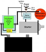
Hi Andy and thanks for insights and suggestions.

After I had posted my last, I noticed the condition you mentioned and sent off an e-mail to the friends who had helped me select the connector. What I also noticed was that In the middle of a contactor switch from NC to NO, a full disconnect of power to the car could take place. This could result in a fall back of the contactor to the NC position and, if the key was still actuated, a repeat of the cycle until the key was released. The car may never start because the NO switch may never take place. Something could be added to the contactor to avert this issue or maybe there is something already in the contactor to address it or maybe it switches fast enough for this not to happen in the first place….something to look into.

Steve also mentioned the Ford solenoid and I came back to the Forum to update my last entry to ask him about it as I would like to find a less expensive alternative to the connector referenced.

I need to consider your other comments as they would also require some changes to the initial presentation. Yes, this is getting complicated but would like to follow this approach to a reasonable conclusion and would appreciate your continued help.

All the best,
Ray
 
Last edited:
Thanks Bob, but the diagram may be a little misleading. It should not be an issue as the breaker could be placed on either side of the connector and the 2 components would be integrated into a single module and installed conveniently close to the battery’s location. Even so, should a short occur between the two as you presented, a fault should be registered by the breaker since a high amperage flow would result and a branch to the NC circuit would be created by the ground short. At least that is what I think.

In the NO connector state, the full circuit is neither restricted nor protected to allow for full amperage problem starts but someone would be initiating the start to monitor the start and sense if there is a problem. If a problem when starting, simply releasing the key would move the connector back to the NC state and the breaker would fault and break the circuit connection to the battery.

I still have to deal with what would happen in the middle of the switch-over from NC to NO and Andy’s point about the alternator not being connected to the battery in the middle of the fall back from NO to NC.

Thanks again Bob,
Ray (64BJ8P1)
 
Just to complicate things further: based on the earlier thread of the stranded fellow and his fried pertronix -- wouldn't the setup also need to have a cutoff for the generator/alternator output to prevent frying the pertronix?
 
Perhaps, instead of disconnecting the circuit breaker during starting, leave it connected and bypass it with a SPST contactor. Then you will continue to have power to the key. The larger and lower resistance wire to and through the contactor will take most of the starting current.
 
John thanks for your response.

The approach you contributed, if I am correct in my understanding, is similar to a thought I had earlier but was concerned that high amperage applied to the solenoid would fault the breaker on a parallel but fully interconnected line. Since you also presented this approach, I want to make sure I didn’t dismiss this approach prematurely and, since I want any approach eventually selected to function reliably and predictably, I decided to test my initial concern.

Parallel%u00252520Circuit.jpg

To test whether the breaker on a parallel connected circuit would not blow, I installed an inline fuse carrier with a 5 amp fuse into a parallel circuit to the positive cable of a set of jumpers. I attached the jumpers to the battery of my Triumph and tried to jump my lawn tractor. The result, the fuse blew each time I tried to jump the tractor.

Although this approach would have a number of beneficial qualities, if the breaker faults every time the car is started, it is truly a non-starter.

However, if this approach did not fault the breaker during start-up, it would have provided the constant power to carry the switch to completion and would provide the alternator/generator with continuous connection to the battery during the switch. It would also be inexpensive and easily implemented.

If the configuration was to function as hoped and a short occurs during the operations state (after start-up), the solenoid wound be open and the breaker would fault. The open connection to the battery would cause the alternator/generator to overcharge but if a 20 amp fuse was fitted to the main power branch to the car (the brown line from the starter solenoid leading to the regulator), I expect it would trip and the alternator/generator would continue feeding the short until it wound down or shorted out. If the fuse faults, I expect all other components would be OK.

If a short happened during start-up, releasing the ignition key would revert to the solenoid to the open state and the operations state scenario should play through as above.

My concern is that the breaker will fault each time you attempt to start the engine leaving you dead in the water.

Ray (64BJ8P1)
 
Ray, if you were using the lawn tractor start solenoid signal wire to activate a second solenoid as per your drawing then it may not entirely be a fair test because of two things. A fuse/breaker will pass a higher current than its rating for a given time before blowing and this current is massively less for a 5A fuse than for a 80A one. It may be perfectly acceptable to pass 1000A through an 80A fuse for 0.01 seconds on a regular basis whereas that might only be 50A for a 5A fuse.

Second, the response time of the lawn tractor solenoid will be faster than the Ford one simply because it is smaller. Response time is mostly governed by the mass of the internal plunger. If the start solenoid gets to the closed position before the safety solenoid does, and the fuse doesn't have much over-current tolerance then it'll be a no show. I'd try the same test with a Lucas start solenoid and an 80A fuse, you may find it works every time.

Andy.
PS I like your engineering approach to this project!
 
Yes, Andy is correct. I think the 5-amp fuse is just too small. Also, your should have a fuse may be either quick blowing or slow blowing. Breakers will all have a time delay.
 
Andy/John,

To be clear, the drawing is the approach implemented on the Healey.

I jumped the lawn tractor by grounding to the frame and applying power directly to the starter. I bypassed the tractor solenoid. I used a standard spade fuse and chose the 5 amp as to eliminate any chance that the approach would not cause a problem. My choice was also to provide a major difference as that in a hard start draw when compared to a standard operational current draw in the Healey.

Andy, along with John, you both still think this will work and the breaker will not fault? I will try some more testing.

Andy, I am still looking at a 40 amp breaker as the 80 amp seems high and would still cause a fire issue. Although I understand your point and the reason for the 80 amp choice, the alternator should be isolated as I already have installed 20 amp circuit breakers on the car’s brown power line from the starter solenoid and have separated and isolated all lights from other power requirements and taped power directly from the alternator and installed a 20 amp circuit breaker here as well. That means if the alternator over-generates, all breakers should fault and the alternator will be connected to nothing and only damage itself. At least that is my thought.

Thanks guys,
Ray (64BJ8P1)
 
By bypassing the tractor solenoid, you allow maximum current to flow through the fuse until the Ford solenoid closes. Ideally, the Ford solenoid should close first and then the starter solenoid. If I remember correctly, the BJ8 uses the key to start rather than the starter button that the earlier cars (like mine) use. You may need to have a separate button to close the Ford solenoid before you turn the key to start the engine.
 
The problem I see with the alternator is that if it is momentarily producing say 65A into a fairly flat battery then all that current (minus a few Amps for the coil and fuel pump etc) will go through your 40A breaker on its way to the battery. When the breaker opens then the battery is isolated from the alternator which is still connected to the rest of the equipment- same scenario the burned out a Pertronix recently. If you put a large diode backwards across the breaker then at least if it opens, the alternator still stays connected to the battery via the diode. Over-voltage from the alternator will not affect any fuses or breakers but it will fry electronics.

As John says, breakers have some form of time delay and you will be utilising this feature to cover any current drawn in the transition to starting position. Be aware also that industrial breakers don't always have much vibration tolerance so if you'd prefer a resettable device over a fuse then make sure it is automotive sourced.

I'm a firm believer in fuses- if it blows then either there is a fault or the system is not designed properly. A fuse should never ever blow and if it does then drill a hole in it and hang it on your keyring because it has very likely saved a large expense of replacing burned out wires, or worse the whole car. If you need to reset your breaker due to a non-fault condition such as charging a flat battery then it isn't working right. A slight aside to this scenario, I was asked not to come back while working on an industrial installation and I noticed that the plant operators arrived in the morning and hit the "reset all alarms" button before making a coffee. There would be a dozen or so fault alarms raised during the night from the process equipment and I couldn't believe that this was normal practice. There should be no alarms under normal conditions! What if one of those alarms was a genuine problem? Kaboom! So I set about writing the control code of the machine I was commissioning to never produce an alarm or error unless it really had a problem. My employer got wind of the fact that I was deliberately blocking process alarm messages during power-on phase and had me removed from the site... Oh well, you can't argue with stupidity. They are now in receivership.

Andy.
 
John/Andy,

First, the diagram is of the approach and not the test. The test did not have a solenoid involved. It only consisted of the jumper cables, a car’s battery and a parallel fused circuit rigged up to the positive jumper cable. The jumpers were hooked up to the car’s battery and the negative cable was attached to the frame of the lawn tractor. The positive cable, and therefore power, was manually applied directly to the tractor’s starter motor. That’s it.

John, I agree with your observation on solenoid application timing and an issue that will definitely need to be addressed. In the approach diagram, the battery solenoid must switch before the starter solenoid and the switch must be dependable and not probable (we can’t depend upon how fast each solenoid switches). The common way to achieve this sequential application is to jumper the signal and power connection on the starter solenoid. However, this will not work on cars wired like the Healey as the alternator/generator feed runs through the solenoid on its way to the battery. Once started with the jumper in place, the starter would continue to run with power to the signal wire provided by the alternator/generator.

Andy, the application of the large diode is an interesting way to provide continuing flow to the battery but block flow from the battery. If the alternator is normally wired (2or 3 wire), once power is cut to the car, it would not be long before the alternator stops functioning. However, during that brief time before it stops, an overcharge spike could be produced if the battery is not connected. The diode would seem to satisfy this issue for this brief period.

Thanks Guys for your critical observations, insights, and suggestions.

Ray (64BJ8P1)
 
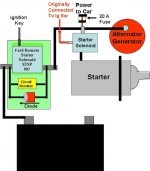
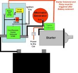
Here are 2 diagrams with the suggestions by John and Andy included.

BCP%u002525201.jpg BCP%u002525202.jpg

Andy, what type of diode should I search for?

Ray (64BJ8P1)
 
Something like this would be fine.

An alternator will keep producing output once it has reached 'excitation' regardless of whether the battery is connected or not. It is pretty much impossible to stop an alternator from charging except by stopping it turning. Even a later type alt with the power on/off wire will still keep charging because the key is still on in the situation where the battery becomes disconnected. The only unknown is how well the internal circuitry can maintain a stable system voltage without the battery connected. Some alternators can... most can't.

For all this added complexity, I have to say that a bit of preventative maintenance of the main cable and perhaps some improved insulation seem a much simpler and more robust solution.

Andy.
 
Andy,

I totally agree that this is getting a little more complex than I expected. However, with your contributions and those of John, and others, I have learned quite a bit and expect that all these components can be assembled into a single small box with only a very few external connections needed for a Healey installation. Although we will be able to address all issues identified and the logic seems appropriate, testing the approach when the unit is completed is something I anticipate will be difficult to do.

On the diode identification, you mentioned they are relatively inexpensive but the one I have identified is a little pricy at $25.88 (https://www.digikey.ca/product-detail/en/150K60A/150K60A-ND/78837).

Ray (64BJ8P1)
 
Back
Top