• Hi Guest!
    You can help ensure that British Car Forum (BCF) continues to provide a great place to engage in the British car hobby! If you find BCF a beneficial community, please consider supporting our efforts with a subscription.

    There are some perks with a member upgrade!
    **Upgrade Now**
    (PS: Subscribers don't see this gawd-aweful banner
Tips
Tips

Am I thinking right? Jaeger electric temp gage.

Lukens

Jedi Warrior
Offline
I can't leave well enough alone so I stripped my TR3's instrument panel to clean up the wiring (it needed it). The PO installed an old Jaeger electric temp gage and a single wire sensor.
I didn't pay attention when I removed all the wiring, but this is how I THINK the temp set-up goes:
1) Hot wire connects to either terminal of gage.
2) Wire from other terminal on gage goes to sensor.
3) Sensor varies resistance to ground (through its threads) as temp changes.
4) Metal strip in gage bends relative to current (heat) and moves pointer.
I can't see that it matters which terminal on the gage I connect to the "key-on" hot wire. Am I right.
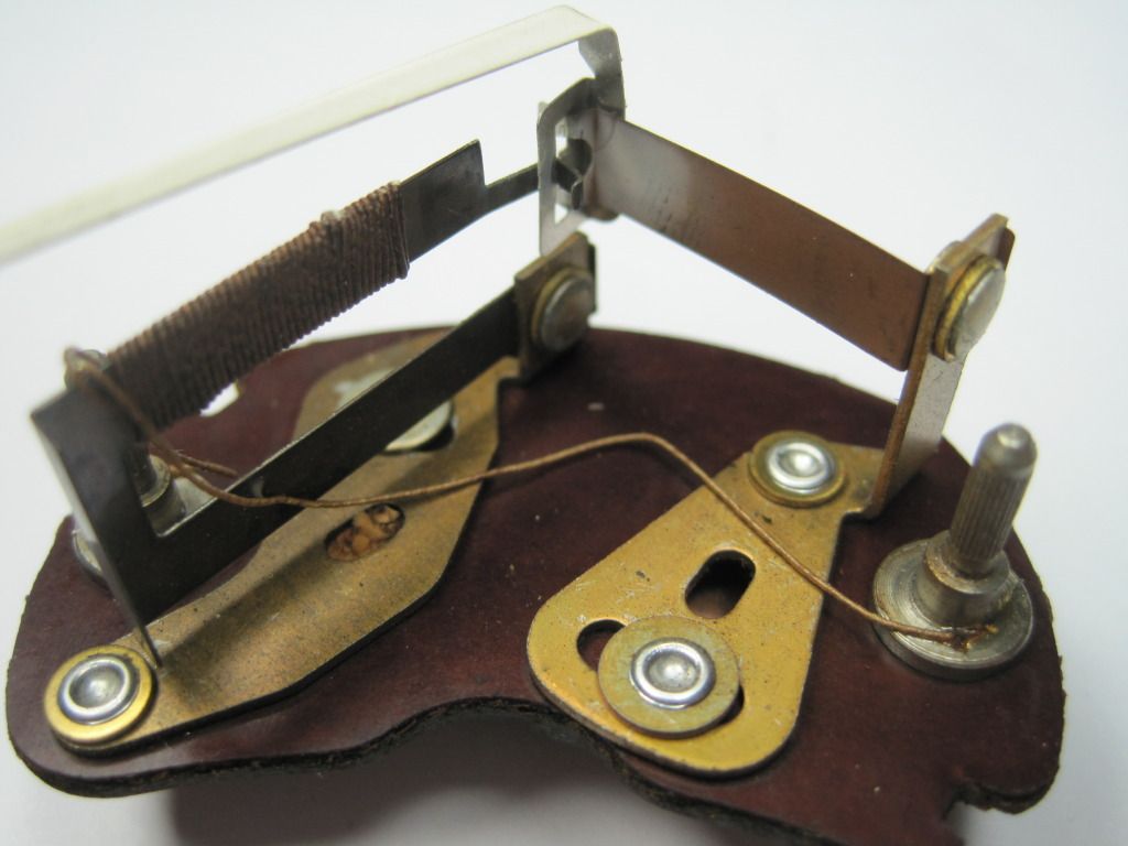
IMG_2202_zps1054355c.jpg

Here's a pic.
 
Yes, you are right. But, there needs to be a voltage "stabilizer" in the circuit and they have definite input and output pins. In addition, some of them are polarity sensitive.
 
With the gauge show in your picture the voltage stabilizer is required as Randall said. The electromechanical ones are not polarity sensitive, the modern replacement electronic ones are. Moss sells both. On the voltage stabilizer there are three terminals. The first is the earth connection via the case. The case MUST be grounded or the stabilizer will pass 12V, not the 10V it is intended to supply. The other two stabilizer terminals are labeled "B" (for battery) and "I" for instruments. As you would expect, "B" receives (typically) a dark green wire, switched from the fuse box. The "I" terminal typically receives lighter green wires which are connected to the electrical gauges. You are correct, with the type of gauge shown in your picture you can connect either gauge terminal to the the stabilizer's "I". The remaining gauge terminal receives the sending unit wire. The type of gauge you show is not polarity sensitive.
 
Thanks Randall and Doug... I'm enlightened again.
Not to look a gift horse in the mouth, but I have to ask. Why is a stabilizer needed when the basic design of the gage itself gives a slow (steady) response. Was it because the gages were all calibrated to 10 volts back then?
Russ
 
Well, sort of. But the reason they were calibrated to 10v was so the voltage stabilizer could be used. The real problem is that the battery voltage is by no means a constant and the gauge is quite sensitive to changes in supply voltage. The voltage stabilizer (which is something of a misnomer) allows the gauge to read the same whether the engine is idling with the headlights on (heavy discharge can cause the battery voltage to drop below 12 volts, plus some voltage drop in the wiring); or is running down the highway in cold weather (generator supplying 14+ volts). The gauge mechanism actually responds to how hot the heating element gets (the coil of wire in your photo above), which in turn is roughly proportional to the square of the voltage applied to the gauge. (power equals voltage times voltage divided by resistance)

But note that the original type voltage stabilizer does NOT supply 10 volts! Instead, its output switches between zero and full battery voltage, such that the average voltage is 10 volts. This works out OK since the gauge responds too slowly to follow the changes; but can be quite confusing if you connect a meter (or a test light) that can follow the changes. In fact, a good operational test is to connect a test light and see if it blinks on and off. The solid state replacements (the ones that are polarity sensitive) don't work this way, but the originals do.

PS, while you have it apart, check that the two sliding levers are snug and won't move easily. When I pulled apart the voltmeter on my Stag (which uses the same mechanism), one of the pivots was so loose that the calibration would move from just a light bump. I had to re-peen the rivets a bit before recalibrating the gauge.
 
Back
Top