Hey Guest!

 Hey - did you know if you click on the title of a thread it will take you to the first unread post since you last visited that thread?
 but were afraid to ask:
  STOP!! Never post your email address in open forums. Bots can "harvest" your email! If you must share your email use a Private Message or use the
  smilie in place of the real @
 Pretty Please - add it to our Events forum(s) and add to the calendar! >>
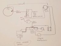
I have installed an alternator in my TR3A rebuild and am getting to the wiring point of the rebuild.
I have a 60 amp Amp meter and have modified the control box so that connections D, A, A1 are tied together so it looks more original. (I think that was Randall's idea).
I got some 60 amp wire from British Wiring.
Plan to use the original solenoid to power the Hi Torque starter solenoid so I retain the posh button on the firewall.
So here is a very rough wiring diagram that I am working on. Please point out all my errors as I am not an electrician.
David