• Hi Guest!
    You can help ensure that British Car Forum (BCF) continues to provide a great place to engage in the British car hobby! If you find BCF a beneficial community, please consider supporting our efforts with a subscription.

    There are some perks with a member upgrade!
    **Upgrade Now**
    (PS: Subscribers don't see this gawd-aweful banner
Tips
Tips

AH EFI build... again

HealeyPassion

Jedi Warrior
Country flag
Offline
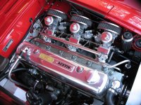
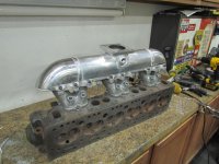
As a few of you know, I built a EFI AH a few years back... a Works Rally Tribute car with EFI (pic. attached). On that car, I went to great lengths to hide the EFI so the engine simply looked like a vintage tri-carb setup (pic. attached). It worked well. I've since sold the car to a gentleman in Australia. Now I'm working on another EFI Healey... another BJ7. This time I decided rather than hide the EFI I was going to try to optimize the injection system without regard to the original look. To that end, I decided to make an intake manifold expressly for injection. You may have seen a short 1 minute video of an initial test we did on the first version of that manifold (and ancillary components). It worked very well but there were some problems with the Weber castings I used, which were completely unrelated to the EFI manifold. Without boring you with details, I decided the, what I'm calling Version 1 manifold, was not going to be the final. So, I got another set of Weber manifolds, from a different source, and began Version 2 of the manifold. Besides being a much more robust casting than the previous one, I changed a number of the design elements to improve injector access. Yesterday, we (Chris Mack of Maxinnovation and I) finished the near final Version 2 EFI manifold for my Healey (pic. attached). It still needs final welding and metal finishing, but you'll get the idea.

The engine is now together awaiting external components (EFI manifold, headers, etc.). The goal is to start the engine on a run-in stand sometime in the next 3 weeks. Besides the EFI stuff, the engine has a head extensively modified by Hap Waldrop (Acme Speed Shop in SC), a custom cam by Dema Elgin (Elgin Cams in CA), rocker arm assembly reprofiled by Gary (Rockers Arms Unlimited in CA), machining by Ridge Reamer in CO, and assembly by Ted Ax (Ax and Allies in CO) and a bunch of other details.

I'll fill you in when we've done the run-in.

MAF-Concours2013 23 DDLs.jpg23 Small 50 Engine 0586.jpgAH EFI Manifold V2 S50 1944.jpg

Steve


Last edited:
Bob, I was at a car show and old warbird airplanes benefit for children fighting cancer and a professional photographer caught this picture. I didn't even know he'd taken it until a year later I saw it on a display he had at another car show! So, now that picture is in my office.... love it!... two period icons! Oh, and "yes" a T-33.
 
Last edited:
Looking good Steve, can't waiting to see the finished project on the road.
 
I know if I walked into my kitchen and put a cylinder head and manifold on the kitchen counter I would be wearing my testicles as earrings:highly_amused::highly_amused:
 
Doug, … and thank you for helping me break the log jam on my rods. Your old race rods will live to run another day!
 
Last edited:
I know if I walked into my kitchen and put a cylinder head and manifold on the kitchen counter I would be wearing my testicles as earrings:highly_amused::highly_amused:

This isn't anyone's kitchen... this was taken in the shop of Chris Mack. I'd know better than to put any engine part on our kitchen counter :smile:
 
Steve it looks like pretty exciting work. My question is from myself, an absolute know-nothing when it comes to EFI, but,
is there a deficiency in putting the injectors close to the exhaust manifold? I realize there may be no options. Thanks.
 
Last edited by a moderator:
Steve it looks like pretty exciting work. My question is from myself, an absolute know-nothing when it comes to EFI, but,
is there a deficiency in putting the injectors close to the exhaust manifold? I realize there may be no options. Thanks.

I'm sure a real engineer could give you a better answer than I can...but here goes. While heat is an issue, it is a completely different environment than a carbureted car. My EFI system has (or will have) a full circulating fuel source. Meaning, I'm pumping the fuel out of the gas tank, routing it through the fuel rail, the pressure regulator (set at 45 psi) and back into the gas tank. So the gas is never sitting still and it is acting as a radiator for the injectors. The fuel rail always has cool gas available to the injectors... unlike carburetors which has fuel sitting in a fuel bowl which can boil and cause vapor lock. So you might ask, why not put the injectors on top to keep the injectors further away from the exhaust headers. The answer to that is that the injectors have been placed to optimize the fuel spray pattern presented to the intake valve (which dictated their position in the runners). If I put the injectors on top, I will be bouncing the spray pattern off the intake runner's floor. While bouncing the spray isn't always a bad thing it does increase the possibility of fuel puddling on the floor of the runner's. We'll be doing dyno testing to see how effective the design is, but initial static testing was very positive.

I might add that I had a similar placement (injectors under the runners) on my last AH EFI system and there were no heat issues (it also had a full circulating fuel system). However, this time the injectors have been moved to a more direct path in the runners so there is still much tuning work to be done.

If there are real engineers out there, not just hobby engineers like me, that can add to this please chime in.

Steve
 
Last edited:
I will add that flow isn't measured in psi. But, flow can be estimated based on the restriction downstream of the regulator. So, is there any restriction in the line going back to the fuel tank? What is the size and length of the line from the regulator back to the tank? We can assume the flow through the injectors based on fuel economy. For example, 60 miles/hour, divided by 15 miles/gallon is 4 gallons per hour.
 
Steve thanks for ur very through explaination. You’ve got a big jump on it.
 
I will add that flow isn't measured in psi. But, flow can be estimated based on the restriction downstream of the regulator. So, is there any restriction in the line going back to the fuel tank? What is the size and length of the line from the regulator back to the tank? We can assume the flow through the injectors based on fuel economy. For example, 60 miles/hour, divided by 15 miles/gallon is 4 gallons per hour.

Of course John is correct fuel flow isn't measured in psi... it's more commonly as gallons per hour (GPH at some psi) which is how fuel pumps are rated... and real world flow in a car would depend on fuel line size and restrictions such as a regulator ... which in my case the lines are -6 AN, which is equivalent to a 3/8" hose and the regulator is set at about 45 psi (exact pressure will be determined by testing... on my last Healey it was 43 psi). All fittings are AN. No offense as you very likely know more about this than I do, but I'm missing the point on flow through the injectors … the fuel is full circulating whether or not the injectors use it... so the fuel is pumped out of the tank and returned to the tank whether or not the injectors use it. The fuel passes over the injector inlet providing a cooling effect on the injector... even if it isn't used... and the fuel that is used by the injector is cooler than it would have been if it was sitting in a carburetor bowl since it is constantly being replenished by fresh/cooler fuel from the gas tank. What am I must be missing regarding flow - fuel economy and heat?
 
.... What am I must be missing regarding flow - fuel economy and heat?
You're not really missing anything. The flow of excess fuel does provide some cooling. How much cooling depends on flow. Whether that is enough flow and cooling is not an easy analysis. Since we don't have the tools readily available for that analysis, you will have to experiment. Worse case is you having to increase fuel flow with a larger pump, or relocate the injectors. If you were Ford or GM, it would make sense to use computer numerical modeling to do the heat transfer analysis, and even then they would experiment to confirm.

As for fuel economy, having excess flow for cooling has a very minor effect on fuel economy.

Okay... all good.... thanks John.
 
G'day Steve,
The "gentleman in Australia" is a good friend of mine and a fellow member of the Austin-Healey Owner's Club of Queensland (even though he lives just over the border in New South Wales!) I have to say that the EFI that you built for that car is a beautiful bit of engineering.
Cheers,
Alwyn

Thanks Alwyn! Hopefully, when all is said and done, someone will be able to say this new project is a "beautiful bit of engineering." Understandably, it will not be to everyone's liking! I'm pretty sure there will be plenty of folks that think what I'm doing is sacrilege. But, in my defense Donald and Geoff Healey were innovators. Donald always drove a modified Healey and Goeff was always tinkering with how to improve the breed. I suspect, they more than most, would approve efforts from technical innovation (or updating if you wish). At any rate, I have saved all the original parts so if at some point someone wants to make it stock again they can.... it won't be me.

Say, "Hi" to your friend for me! His car is very much alive in this one.

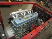
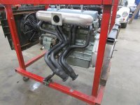
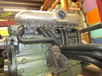
Here are a few images of the current status of the engine build.

Cheers,
Steve

AH EFI on stand S50 1956.jpgAH EFI on stand S50 1958.jpgAH EFI on stand S50 1959.jpg
 
With the welds are cleaned up that really looks impressive!!

I can also see that the injectors won't be that close to the headers. Perhaps a bit of header wrap or heat shield may be needed after testing.
 
Back
Top