• Hi Guest!
    You can help ensure that British Car Forum (BCF) continues to provide a great place to engage in the British car hobby! If you find BCF a beneficial community, please consider supporting our efforts with a subscription.

    There are some perks with a member upgrade!
    **Upgrade Now**
    (PS: Subscribers don't see this gawd-aweful banner
Tips
Tips

Adding an O2 sensor to exhaust?

Norton47

Jedi Warrior
Offline
Didn't I see some posts about adding a O2 sensor to the exhaust for tuning purpose's. One that could be read on an voltmeter?
I have a bad ear so if this can help in setting carbs and I have my exhaust off and am planning on going to the welder to strengthen the rear differential mounts, now would be the time or to at least put in the provisions.
 
Last time I checked, Paul Tegler installed a 5 wire O2 sensor on a Spitfire. He cut a hole in the exhaust header for the sensor bung.

I was described, with photos, on his website: teglerizer.com

It's probably in the "Triumph" section. I saw it in action, pretty interesting. Allows for very fine engine/carb tuning.

Let us know . . .
 
Here is what the welder did. Depending on the unit, you need to be somewhere less than 30" from the cylinders, so check to see where you need it to be mounted in that respect.
 
The O2 sensor only has to be close to the cylinders if you use a one wire sensor. The one wire type relies on the exhaust to heat them up to operating temperature. If you use a four wire heated sensor, they can be mounted much further downstream, as they have their own heat source.

Although, 30" is a considerable distance away. I don't know if a one wire will work effectively that far away.
 
Art,

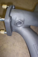
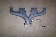
Mine is the five (5) wire preheated version and they still recommend in the manual that it be within 12"-48" of the cylinder head. I will requote the actual information from the instruction manual, as I read the 30" from another source, but can't accurately quote it.

Copied from the NGK A/F Ratio Kit instruction sheet:

"Below are recommended guidelines for installing the AFR sensor. Some exhaust configurations may make it difficult to meet each of the recommendations exactly, and some compromise in mounting may be required. The sensor does not necessarily have to precisely meet every mounting guideline below to operate, but please understand that the better you conform to these rules, the longer the sensor will last and the more accurate the results will be.

The AFR sensor should be located between 12” and 48” from the engine, upstream of any catalyst device if so equipped. The closer the sensor is to the engine, the more likely it will be overheated, possibly shortening its life. The further it is from the engine, the more likely condensed water will get into the sensor and thermally shock it, again possibly shortening its life. The sensor should be mounted at least ten exhaust diameters upstream of the exhaust exit (ex. for a 3” exhaust pipe, that is 30”). If the sensor is mounted between one and ten exhaust diameters from the exhaust exit, the AFR measured will be leaner than the actual AFR by as much as 2 AFR at low engine speeds (i.e. less than 3000 rpm).

Make sure there are no leaks in the exhaust system, as this will create an artificially lean (higher) AFR reading. Also, install the sensor upstream of any factory air-injection if so equipped, as this too will cause a false lean reading."
 
Thanks for that info Brosky. 48" is quite a distance, and 12" is pretty close. So the distance with a heated unit is pretty liberal. I do know that the one wire sensors need to be close, as they are relying on the heat of the exhaust to get them to function. All cars being made now come equipped with two sensors for each bank of cylinders. One before the cat that sends info on the AFR to the ECU, and one AFTER the cat to report on how effective the cat is doing it's job. That second sensor can get quite far away from the cylinders. Although four feet is quite a distance.

I'm going to be installing an O2 sensor on my TR3, and it will be heated, but it will be a four wire. Can you tell me what is the difference between a four wire and a five wire sensor?? I have not heard about the five wire units.

So what I get form this is that the sensor is best located ten or more (not too much more) diameters from the exhaust ports on the head. Is that correct??
 
Art,

My day for bad quotes. From the digital box harness, there are four wires to the sensor (you are correct) and two coming off for power and ground (which I didn't count because they power the digital box) and TWO wires (not one-my mistake) that go to a Volt Signal pickup and a Ground.

The extra wire(s) on mine can go to an auxiliary meter that will measure voltage and convert to a reading. With the readout that I have, I still can't figure out why anyone would want to do that, since it's not a computer data link.
 
We added the one wire Oxygen sensor on our Spitfire in the hole for the Air pump. Cheapest one from Autozone.

The wire was extended to the cabin where you use a 0-1 volt voltmeter to read the Oxygen.

We also did this on my sons 1969 Chevelle 454.

Great trick. Look at the bottom of this article.

https://www.bob2000.com/carb.htm

Larry
 
OK, Larry, so you're reading in MV at the very low end of the scale. Now I get it.

I just couldn't get the relationship to the voltage and now that I see the chart based on rich/lean, I understand.

Sorry, too many years of GM & Lexus flat rate plug and test tools. Either good or bad, swap it out and get the car on the road. All of our chips for performance were "plug & pray" back then as well.

That's a good tuning article, by the way. Thanks!
 
Ditto on tomkatb's article; even if you don't have a Holley. Like to see a write up like that for the Stromberg 175 CD; the "Buckeye" article notwithstanding.
 
Thank you all, I spent several hours surfing the web and researching O2 sensors. I found several DIY sites that will take the millivolt levels and light led's, instead of reading a voltmeter.
This is more or less what I was looking for, some thing to help basic tuning. Most importantly I do know that I need to but the bungs in now, the rest can come along later or in stages.
Here is an interesting site. https://www.scirocco.org/tech/misc/afgauge/af.html
I currently am not interested in an in car display but rather a tuning aid.
 
Now that is a great way to use a spot that no one really needs for anything. I never listen to my radio and still wonder why I went to the trouble of putting a new one in.

Of course it does come in handy for blasting oldies at a car show, but never while driving.
 
I installed a 1-wire sensor in the exhaust manifold. I put it in this spot on the two pipe manifold because there is a crossover hole that will allow the sensor to read from all cylinders. This one is for fuel injection, but I did the same thing on a Chevy truck using a guage from Summit that used red/yellow/green leds to show mixture.
 

Attachments

  • 8766.jpg
    8766.jpg
    28.5 KB · Views: 135
  • 8767.jpg
    8767.jpg
    25 KB · Views: 142
I've got one of these Westach AFR gauges installed in my supercharged Miata. I like the analog display. This meter is buffered, so the needle doesn't swing back and forth eradically like the LED displays do when used with electronic fuel injection. I would imagine that with carbs, there wouldn't be the constant dithering.

I'll most likely be using this gauge in the TR3. It's not cheap, but it's nicely made and looks good..
 
I think but am still learning, that some of the dithering could be caused by the closed loop system for fuel regulation control on an ECU/EFI system.
I think, that with a naturally asphyxiated carburettor, a Air Fuel sensor being used in the monitor mode, would not have that dithering. I am sure that there would be some based or caused by engine operation and wear. I am going to add the bungs and at least plug them for now.
I believe I will add 2 in the exhaust down pipes. I have read at least on the narrow band sensors you can arrange a switch to read between the two,or if I build my own monitor I will build a double display.
 
The big question I have on this is, what good is one sensor on a car with two carbs. To be any use you need to have one for the first cylinder #1, and one for the last #4 or #6 depending on the car. If you use one sensor after the pipes merge you only get an average reading of the mixture. One carb can be lean and the other rich and the reading would show good.
On a TR3 there isn't anywhere on the manifold that is over 12" away from the port so you would have a very short sensor life.
I thought this was a great idea until I thought about getting good info for each carb. I guess you could use the sensor after you used a color-tune to balance between the carbs.
 
Well, that's a bit different set of requirements than a later model TR6.
One thought though would be to put the bungs and plug them and only use to tune. Then remove. To me there is limited use of the display in the cockpit.
 
Back
Top