• Hi Guest!
    You can help ensure that British Car Forum (BCF) continues to provide a great place to engage in the British car hobby! If you find BCF a beneficial community, please consider supporting our efforts with a subscription.

    There are some perks with a member upgrade!
    **Upgrade Now**
    (PS: Subscribers don't see this gawd-aweful banner
Tips
Tips

62 tri-carb wiring harness

  • Thread starter Deleted member 21878
  • Start date
D

Deleted member 21878

Guest
Guest
Offline
one of my next projects is to install the wiring harnesses. i am looking for pictures, tips or any help i can get for laying them out and getting them attached. where they need to connect to each other, etc.

Thanks
 
The schematic in the shop manual--available online somewhere, I presume--is absolutely necessary. Are you working with a complete car, or bare chassis? Either way, the logical starting point is the the big branch--sort of like an aorta--that splits to go under into the dash and either side of the engine bay, and a longer section that goes along the left-side chassis rail to the boot (battery-starter solenoid cable goes along the RH side). Lay the harness out flat and you'll see what I mean. A P-clip to hold the harness will go in almost any place there is a small, unthreaded hole about 1/8" in diameter on the chassis (takes a #10 sheet metal screw; posidriv if you want to go concours). I think BCS has a photo set that might help.
 
I just finished installing a new harness and have some tips:
--get one of the full-color large size wiring diagrams from Tom's Toys
--get a label maker (such as the Dymo LabelManager 160 $14 on amazon)
--referring to the diagram, label all the wire ends; I had to staple the labels to keep them from separating. You can do this in the comfort of your living room - this minimizes confusion time lying on your back looking up under the dashboard.
--I found it helpful to test the wires for continuity to figure out, for instance, which wire to a switch was the supply side and which was the output side.
--the big stretchy firewall grommet is 281-900. I found the one in the grommet set to be too stiff to stretch over the harness.
--BCS sells complete P-clip sets for the different Healey models for around $80.
--I wound up with an extra set of grommets, which was useful as I ruined a couple of them.
--many of the P-clips are attached to captive 10-32 nuts. Since I wasn't going for concours, I bought a supply of stainless 10-32 screws in 1/2", along with some in 5/8 & 3/4. A supply of #8 and #10 sheet metal screws will see you through. Buy these in bulk from suppliers such as FMW Fasteners or Bolt Depot. Also lots of #10 lockwashers - I like the internal stars.
--since I'm running 5-spd, I removed the O/D wiring, leaving a number of threaded holes in the firewall - plugged with 10-32 SS setscrews
--before installing the heater, make sure the wiring is the way you want it and plug all the air leaks in the firewall
--I made a conduit from 1" thinwall alum. tubing, which runs across the heater plenum behind the heater. This makes it easier to snake accessory wires behind the heater box
LabelsWiring.jpg


Your crimp tool should have the little point at the yellow arrow:
crimpTool_close.jpeg


Made a separate harness for grounding the gauge lamps. IMO they're poorly grounded through the mounting clamps:
GaugesGroundHarness.JPG
 
I did this about 7 years ago, and the advice offered so far is good. The only thing I would add is that my harness had the big grommet for the firewall already on the harness. Hopefully, yours will too. As Bob said, that's the place to start. Also, if you have the old harness, don't throw it away. I remember that there were several fittings under the dash (I think for instrument lights) that were incorrect on the new harness. I was able to splice (solder and heat-shrink tubing) the correct fitting from the old harness. This keeps the wire colors correct with only a small section of heat shrink to give away the repair. There will be several sub-harnesses as well. Get a big wiring diagram and just follow the colors to figure out how the sub-harnesses connect to the main harness. I have take a few pictures or answer specific questions as you go along since my car should be identical.
 
Caveat: The last harness we bought--for our BN2--had one wire colored incorrectly. It was the lead to one of the rear turn/stop lights; when activated, the opposite light was lit. I spent three days trying to figure out what was wrong, even disassembling the relay box and checking and cleaning the contacts. This really ticked me off because I had gotten every connection correct--working just from the schematic and some photos we'd taken--and everything should have worked the first time.
 
Thanks to all. really helpful.
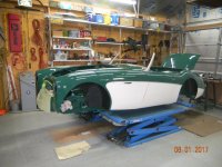
Bob, i will include a pic of my car below to help. but basically it is stripped down. Not trying to do a concours. but a nice driver. i do have a schematic but only a little one. i will look into a larger one. i had looked at the pics on BCS but i forgot about them. i will go back.

Steve, great tips. i am going to write those down. liked the conduit idea also. did you just bolt it to the top with a pipe fasteners?

Keith, thanks for the offer. i could really use the help as i get to the engine bay area and under the dash. everything is a mystery to me there. if you have an email i might be able to use to just ask for some info, that would be great. or can i PM here and does that work better for you?

my new harness has the grommet on it. it was actually semi in the car when i got it but i have since pulled out to do some other work. i also have the old harness in a box. i figured i would pull it out and lay on the floor for help. a lot of the relays and switches are still attached to it.

My main thing now is to just get the routing down to where it should go and also getting the harnesses attached together. main thing is i don't want to put it in and find i should have done something else first... like piping.... ? i did mount all my heat shields. i was sure nothing went behind them. DSCN0134.jpg
really the only thing i have in so farIMG_0152.jpg
i have pulled the rear harness up under the car and screwed it to the frame up to the front. all the lines and the wiring that went from front to back i pulled out so i had plenty of pictures to reference. but once i get forward of the rear, it is all guess work for me.
 
Thanks to all. really helpful.
Keith, thanks for the offer. i could really use the help as i get to the engine bay area and under the dash. everything is a mystery to me there. if you have an email i might be able to use to just ask for some info, that would be great. or can i PM here and does that work better for you?

PM with email address sent.
 
One quick question that comes to mind. If I were to convert to negative ground and go to an alternator, is there anything I should change or lay out for when getting the harness in place?
thanks
 
For an alternator conversion just arrange wiring per schematic. If you're trying for an "as original" look, plan to convert the regulator into a terminal bus. Folks refer to this as a "gutted" regulator which effectively connects the wires screwed externally on the box. A second 10G wire (yellow) was added to the alternator output terminal direct to battery terminal on starter solenoid. The alternator conversion I chose was a Dynamator which looks like the original old generator. Testing it now in SoCal 90+F days. Output is a steady 14.6 amps from 1500RPMs. A Flex Fan is installed for improved under-hood air movement. GONZO
 
Back
Top