Hey Guest!

 Hey - did you know if you click on the title of a thread it will take you to the first unread post since you last visited that thread?
 but were afraid to ask:
  STOP!! Never post your email address in open forums. Bots can "harvest" your email! If you must share your email use a Private Message or use the
  smilie in place of the real @
 Pretty Please - add it to our Events forum(s) and add to the calendar! >>
Have placed the fuel vapor recovery system into complete service on the TR-6. The lines to the carbs and the valve cover were in place, but the line from the fuel tank was plugged at the beginning of the steel line at the fuel tank end. Cleaned all that out and this line is now free to the carbon vapor collection tank. Have also installed the oil vapor recovery system by Good Parts (www.goodparts.com) and an electric fuel pump.
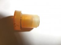
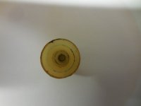
The diagrams call for an orfice (restrictor) in the vapor line from the fuel tank to the carbon canister. I cannot find one available from the parts suppliers so I made one with my 3D printer. Taking a shot at the level of restriction I put a 1.7mm hole in my unit. My question is "Does anyone know the size of hole (orfice) required for the restriction or is the restrictor constructed by another method such as baffles." I can 3D print almost anything so find out what was the original construction would really help.
If I get a good design I will put the STL file here on a post so anyone with a 3D printer, or access to one (friend) can print one out.
Thanks
Dean Hagerty