Hey Guest!

 Hey - did you know if you click on the title of a thread it will take you to the first unread post since you last visited that thread?
 but were afraid to ask:
  STOP!! Never post your email address in open forums. Bots can "harvest" your email! If you must share your email use a Private Message or use the
  smilie in place of the real @
 Pretty Please - add it to our Events forum(s) and add to the calendar! >>
Tinkerman
Darth Vader
Offline
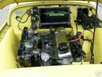
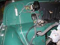
I'm mounting such things as the control box, fuse block, flasher and starter solonoid and I have some questions. I think I know where it all goes except for the fuse block. Does anyone have a picture of where all of that should be mounted? A picture of the wiring harness showing where it comes through the fire wall would be great also.
Does the solonoid need to be isolated wirh rubber grommets? The mounting holes seem to be quite large, about 9/16" in fact.
I see some spire nuts on the firewall in the right spot for where the control box goes. A picture that I have shows what seems to be pan headed screws, anyone know what size?
Where does the horn relay go? I think I just answered my own question. The lucas horn manual shows a horen relay for the 6 volt but not the 12 volt system.
Thanks for any info anyone can provide, Tinkerman