 but were afraid to ask:
 The pulley alignment on my car is off by about 1/4". The pulley on the generator is out to far, or the waterpump pulley is to close. The generator mounting bracket can only go on one way so that's not it. The generator can only fit on the bracket one way so that can't be the problem. The generator does not have the correct date code for the year, could that be the problem? Date code 12-66 22700L C40. The water pump is an original pump rebuilt by East Coast Jag. The only fix I can see would be to shorten the generator mounting pedistal, but that moves it back even closer to the exhaust manifold. I know over the years many things get changed on these cars. Other than the pump, bracket or waterpump housing what else could be the problem?
-
 Hi Guest!
You can help ensure that British Car Forum (BCF) continues to provide a great place to engage in the British car hobby! If you find BCF a beneficial community, please consider supporting our efforts with a subscription.
There are some perks with a member upgrade!**Upgrade Now**
(PS: Subscribers don't see this gawd-aweful banner

Tips
- We have a special forum called "Member Articles" where you can submit actual articles for consideration for publication. Learn More
- Don't have an Avatar? If not, your avatar will default to the 1st character in your username. Go into "Account Details" to change your Avatar.
- Some basic forum navigation info: click
 Hey - did you know if you click on the title of a thread it will take you to the first unread post since you last visited that thread?
- Hey Guest - Is your British Car Club in our Clubs database? If not, send me a PM - Basil

- Looking for a local club? Click the "Clubs" tab above and browse hundreds of clubs world-wide.
- Add Android or iPhone APP: click
- Did you know - any picture or video you add in your posts in any marque-specific forum will also get added to the Media Gallery automatically.
- A few more tips about posting and replying: click
- Hey there Guest - be sure to keep your profile page up to date with interesting info about yourself: learn more
- More tips and tricks on Posting and Replying: click
 STOP!! Never post your email address in open forums. Bots can "harvest" your email! If you must share your email use a Private Message or use the
  smilie in place of the real @
- Want to mention another member in a post & get their attention? WATCH THIS

- So, you created a "Group" here at BCF and would like to invite other members to join? Watch this!
- Hey Guest - A post a day keeps Basil from visiting you in the small hours and putting a bat up your nightdress!
- Hey Guest - do you know of an upcoming British car event?
 Pretty Please - add it to our Events forum(s) and add to the calendar! >> Here's How <<
- Hey Guest - you be stylin' Change the look and feel of the forum to fit your taste. Check it out
- If you run across an inappropriate post, for example a post that breaks our rules or looks like it might be spam, you can report the post to the moderators: Learn More
- If you would like to try some different "looks" or styles for the site, scroll to the very bottom, on the left and click the Style Selector.
You are using an out of date browser. It may not display this or other websites correctly.
You should upgrade or use an alternative browser.
You should upgrade or use an alternative browser.
TR2/3/3A 1956 TR3 fan pulley alignment is off
- Thread starter mallard
- Start date
Hi Mallard I own two tr3s and both of them are like that. I drew the same conclusion you did and at the end of the day, I left it. We had a similar discussion awhile back and a couple others noticed it also. Nice job on that engine ect. I am curious; the bracket on the generator bolt is that original ?
Steve
Steve
Well after further examination I saw that the generator pulley and the crank pulley align just fine. It's the water pump that is out of alignment I think.
Steve the arm did have a locking tab on it. I may have a picture of the original engine with it there. The one in the picture is one that I made in 15 minutes, Moss wants $7.50 for it. Part number 838-560. You have a good eye for originality.
Steve the arm did have a locking tab on it. I may have a picture of the original engine with it there. The one in the picture is one that I made in 15 minutes, Moss wants $7.50 for it. Part number 838-560. You have a good eye for originality.
TR3driver
Great Pumpkin - R.I.P
Offline
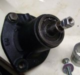
I'm pretty sure that, with the original pump, there is no way to install the pulley too far. The boss inside the pulley is supposed to be clamped firmly against the inner race of the outer bearing, which in turn abuts firmly against the distance piece inside, a small spacer and a circlip on the shaft. This is important, I believe, as the pulley flexes just a bit and will eventually work its way loose if not clamped firmly.
However, there may be some aftermarket pumps that require a spacer installed between the pulley and front bearing, which may have gotten lost. That doesn't seem to be the case here, though, as the shaft would be sticking out of the pulley. The only other possibility I can see is that the shaft is too deep in the housing (meaning the circlip is not against the inside bearing), or it was rebuilt with a shaft that is too short. So I don't know what to suggest, except trying a different pump.
BTW, the lock tab visible on the arm is as original. Stanpart (& TRF) number 106706. However, the tab should be turned up so it locks the bolt head.
Perrymip
Jedi Hopeful
Offline
<div class="ubbcode-block"><div class="ubbcode-header">Quote:]there may be some aftermarket pumps that require a spacer installed between the pulley and front bearing[/QUOTE]
This sounds right to me. I ultimately looked back and discovered a spacer on the (old, replacement) pump/pulley.
If alignment of the pulleys is at issue, it seems to me that the water pump/pulley would be the most likely culprit, not the generator nor the pulley/hub on the end of the crank.
This sounds right to me. I ultimately looked back and discovered a spacer on the (old, replacement) pump/pulley.
If alignment of the pulleys is at issue, it seems to me that the water pump/pulley would be the most likely culprit, not the generator nor the pulley/hub on the end of the crank.
TexasKnucklehead
Jedi Knight
Offline
Well, I've never found Randall to be wrong before, but in this case, I think otherwise. The statement about the distance piece, cir-clip and spacer is correct, and it keeps the impeller positioned the proper distance from the housing (assuming it was soldered onto the shaft in the proper position), but the pulley has no stops or seat. The pulley is held from moving in/out by the nut on the end, and the key. It can be pressed on farther until it bottoms out on the race, or not quite as far. -Then again, just because some of my water pumps had the grease zerts, doesn't mean they were of the original type. The parts manual shows the key as "Key, locating pulley on spindle".
I think you could send it back to the re-builder and have it corrected. Your project looks really nice.
Jer
I think you could send it back to the re-builder and have it corrected. Your project looks really nice.
Jer
Attachments
TR3driver
Great Pumpkin - R.I.P
Offline
Take a look at your pulley, you'll see that the slot (aka keyway) goes all the way through. That means it cannot be located fore/aft by the Woodruff key (the key only keeps it from turning).
Being somewhat curious myself, I pulled apart the pump from TS13571L (which is either original or a very old replacement). As you can see, the pulley was tight against the bearing race.

Suit yourself, of course, but I predict that, if you leave the pulley pushed forward on the shaft (meaning it is not clamped between the nut/washer and the bearing race), it will eventually come loose and ruin both pump and pulley. And the radiator if you aren't lucky.
BTW, there is some variation in how far the impeller protrudes:
Original :

Aftermarket 4 blade (from Moss circa 1990)

"Improved" 6 blade (from BFE circa 2000)
Being somewhat curious myself, I pulled apart the pump from TS13571L (which is either original or a very old replacement). As you can see, the pulley was tight against the bearing race.
Suit yourself, of course, but I predict that, if you leave the pulley pushed forward on the shaft (meaning it is not clamped between the nut/washer and the bearing race), it will eventually come loose and ruin both pump and pulley. And the radiator if you aren't lucky.
BTW, there is some variation in how far the impeller protrudes:
Original :
Aftermarket 4 blade (from Moss circa 1990)
"Improved" 6 blade (from BFE circa 2000)
vivdownunder
Jedi Warrior
Offline
Keith, Lucas C40 generator #22700L (Lucar connectors) is a later model for a 4 potter, but the pulley looks to be too far away from the genny fan.
I've just measured my spare C40 generator #22715 (ex TR4A) and the gap between the pulley and fan is 2mm. Your genny pulley isn't on back the front is it ? - the three lugs on the pulley should face to the front. Or maybe the pulley is not fully home on the shaft.
See you have the rare tropical fan. Ideally these should have been fitted as standard to all exports to hot climates.
Regards,
Viv
Geo Hahn
Yoda
Offline
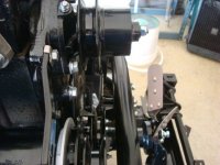
Both my TRs are like that, here's a look at the TR3...

Yes Steve, you need that locking tab for the bracket bolt. I drove for years w/o it then somewhere on a 1000 mile trip the bolt fell out. Didn't even notice it until I was home -- dynamo worked fine just held by the lower mounts but that can't be good for it.
Like Keith -- I couldn'e see paying 7 bucks for something so simple, made on out of a fender washer I already had. Couple of minutes with the grinder was all it took.
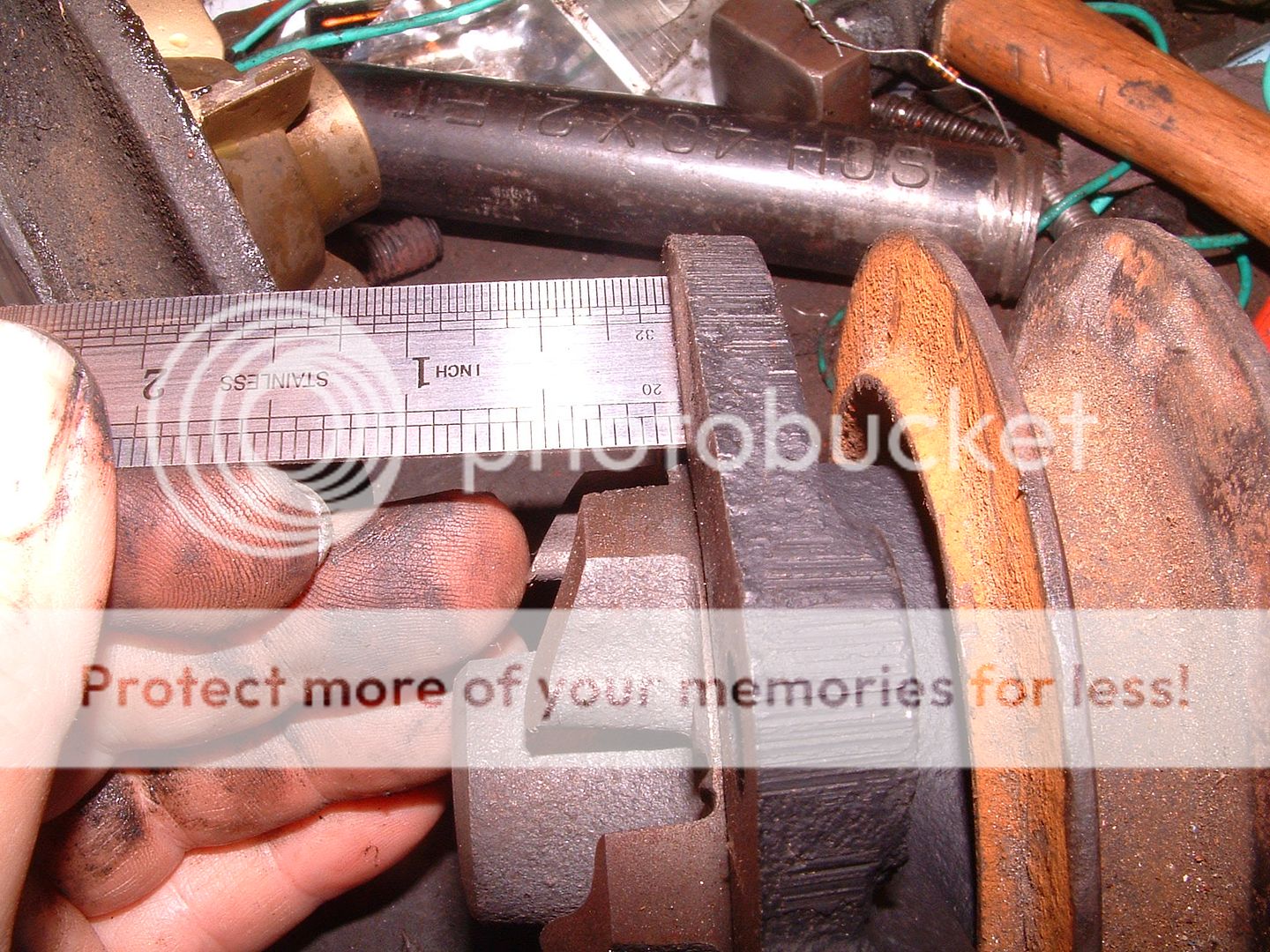
I went and got all the measurements from the original pump and they are all the same as the rebuilt pump. I'm using the original pulley from my old water pump on the rebuilt pump. I don't see how unless the pump pulley is not correct. I will try to compare another pulley with mine and see if the area with key slot measures the same. I don't have an extra pulley so I will have to find one. Or can someone measure one for me. Mine measures 0.983". I did measure the gap between the generator pulley and fan and came up with 3.4mm not the 2mm that Viv mentioned. This could help the problem but would be far from solving it. To make the alignment perfect I need to pull the water pump pulley out 1/4"
Steve said he and others have had similar problems with this alignment and they just left it alone. I'm afraid this would not be good for the bearings in the pump and generator. Well it's time to go eat some Turkey and watch football.
Steve said he and others have had similar problems with this alignment and they just left it alone. I'm afraid this would not be good for the bearings in the pump and generator. Well it's time to go eat some Turkey and watch football.

Offline
Mine, too!mallard said:George thanks for the picture, mine looks exactly the same.
vivdownunder
Jedi Warrior
Offline
On my 3A with correct fanbelt alignment, here's a few benchmark measurements -
Crank pulley. Rear sheave to timing case - 24mm. Measured just underneath the timing tang.
Water pump. Rear sheave of pulley to gasket edge of housing - 28mm. Measured on the RH side up near the top. (My w/p has no grease fitting)
Generator. Using a straight edge on the front engine plate behind the genny. Engine plate to rear sheave of genny pulley - 65mm.
All measurements taken as best possible given the tight space, and might help identify which pulley is the culprit.
Regards,
Viv.
TR3driver
Great Pumpkin - R.I.P
Offline
Here's what mine looks like. This is the 6 blade aftermarket pump, but the original pump looked about the same installed. You can see a larger version at
https://i258.photobucket.com/albums/hh260/TR3driver/TR3-4%20Water%20Pumps/DSCF0002-1.jpg

BTW, I ran with an alternator that was perhaps 1/4" out of line for several years. Didn't have any problems except the belt life was kind of short. After the second heavy duty truck belt broke suddenly (and threw steel cores all over the place), I modified the alternator mount for better alignment and haven't broken a belt since.
https://i258.photobucket.com/albums/hh260/TR3driver/TR3-4%20Water%20Pumps/DSCF0002-1.jpg
BTW, I ran with an alternator that was perhaps 1/4" out of line for several years. Didn't have any problems except the belt life was kind of short. After the second heavy duty truck belt broke suddenly (and threw steel cores all over the place), I modified the alternator mount for better alignment and haven't broken a belt since.
Viv Thanks for taking the time and getting those measurments. These are the measurements I got.
Crank pulley 23.48mm
Water pump pulley 23.50mm
Generator pulley 62.00mm
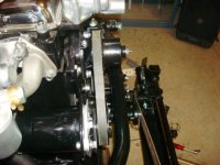
As you can see the crank is about the same, the water pump is off buy the 1/4 inch I've been talking about and the generator is close to your measurement. I ran a straight edge over the face of the generator and crank pulley and they are almost perfect. Not sure how I can correct this without lengthening the water pump shaft. The shaft from the rebuilt unit is exactly the same as the original. With the belt on, the alignment does not look that bad. My picture is very much like George and Randall's
Crank pulley 23.48mm
Water pump pulley 23.50mm
Generator pulley 62.00mm
As you can see the crank is about the same, the water pump is off buy the 1/4 inch I've been talking about and the generator is close to your measurement. I ran a straight edge over the face of the generator and crank pulley and they are almost perfect. Not sure how I can correct this without lengthening the water pump shaft. The shaft from the rebuilt unit is exactly the same as the original. With the belt on, the alignment does not look that bad. My picture is very much like George and Randall's
Attachments
TR3driver
Great Pumpkin - R.I.P
Offline
Maybe I'm missing something, but it looks to me like there are enough threads leftover that you could insert a spacer between the pump & front bearing as I suggested before. You might need to use a center-lock nut or Loctite instead of a Nyloc, though.mallard said:Not sure how I can correct this without lengthening the water pump shaft.
In the picture the pulley is held on with a very thin washer and regular nut. The original set up was a thick washer and a nyloc nut. My concern with the spacer idea is that the pulley would not be making contact with the shaft on the end where the threads start. I was thinking that if I made a spacer that would fit tight over the threads and against the inside of the pulley it would eliminate any side pressure. I don't want the pulley to cut into the shaft, or the hole in the pulley to be ovaled out.
TexasKnucklehead
Jedi Knight
Offline
Randall, you often amaze me. I'm sure you're right and the picture certainly shows the pulley was against the race. I'm not sure it has to be, as the fit between the shaft and the pulley is very tight. -But (as you said) I'd hate to find out the hard way.
So, I must agree that Keith (Mallard) could employ a spacer between the pulley and the bearing and still have enough threads for a nut to hold. Mallard, I think you're thinking the spacer goes on the end of the shaft near the nut, but it doesn't. You need to pull the pulley completely off and install a spacer before the pulley goes back on. The spacer should rest against the bearing inner race at the bottom of he shaft. The little bit of pulley near the threads that will not have shaft touching inside, will not be an issue.
So, I must agree that Keith (Mallard) could employ a spacer between the pulley and the bearing and still have enough threads for a nut to hold. Mallard, I think you're thinking the spacer goes on the end of the shaft near the nut, but it doesn't. You need to pull the pulley completely off and install a spacer before the pulley goes back on. The spacer should rest against the bearing inner race at the bottom of he shaft. The little bit of pulley near the threads that will not have shaft touching inside, will not be an issue.