Hi Guest!

 Hey - did you know if you click on the title of a thread it will take you to the first unread post since you last visited that thread?
 but were afraid to ask:
  STOP!! Never post your email address in open forums. Bots can "harvest" your email! If you must share your email use a Private Message or use the
  smilie in place of the real @
 Pretty Please - add it to our Events forum(s) and add to the calendar! >>
After pulling apart the front suspension on my 100/6 to replace bushes and the like, I have a conundrum in terms of the resulting wheel alignment.
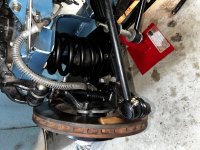
Works completed were essentially to pull all the front suspension apart to replace the following:
Upon reassembly it has become apparent that the front wheels have developed significant toe out (visible to the naked eye), and subsequently measured at about 1/2" (12-13mm) each side measured from front to rear of each wheel on the rim (using the "string line" method to verify). Notwithstanding that the suspension has been dismantled and reassembled, it is not obvious how such a change in the wheel alignment could have occurred. The cross tube was not touched and was reattached at 22.5" centre to centre (which seems to have been stated as a typical number on a previous post I have read).
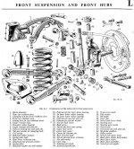
I can adjust the cross tube to bring the wheels into alignment, but it would require shortening as it is at the limit of its adjustment inwards at the moment. However, I am concerned that something might be amiss as the result of the reassembly and therefore I am reluctant to start adjusting the cross tube length in case something has been reassembled incorrectly. Noting that everything seems to be in its correct place and reassembled in accordance with Section L of the Workshop Manual.
Any thoughts on the above would be much appreciated.
Works completed were essentially to pull all the front suspension apart to replace the following:
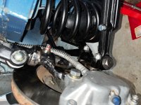
- lower fulcrum pins and rubber bushes
- trunnion pins and rubber bushes
- trunnion bearings
- replace steering box oil seal and top felt bush
Upon reassembly it has become apparent that the front wheels have developed significant toe out (visible to the naked eye), and subsequently measured at about 1/2" (12-13mm) each side measured from front to rear of each wheel on the rim (using the "string line" method to verify). Notwithstanding that the suspension has been dismantled and reassembled, it is not obvious how such a change in the wheel alignment could have occurred. The cross tube was not touched and was reattached at 22.5" centre to centre (which seems to have been stated as a typical number on a previous post I have read).
I can adjust the cross tube to bring the wheels into alignment, but it would require shortening as it is at the limit of its adjustment inwards at the moment. However, I am concerned that something might be amiss as the result of the reassembly and therefore I am reluctant to start adjusting the cross tube length in case something has been reassembled incorrectly. Noting that everything seems to be in its correct place and reassembled in accordance with Section L of the Workshop Manual.
Any thoughts on the above would be much appreciated.