
-
 Hey Guest!
British Car Forum has been supporting enthusiasts for over 25 years by providing a great place to share our love for British cars. You can support our efforts by upgrading your membership for less than the dues of most car clubs. There are some perks with a member upgrade!**Upgrade Now**
(PS: Upgraded members don't see this banner, nor will you see the Google ads that appear on the site.)

Tips
- We have a special forum called "Member Articles" where you can submit actual articles for consideration for publication. Learn More
- Don't have an Avatar? If not, your avatar will default to the 1st character in your username. Go into "Account Details" to change your Avatar.
- Some basic forum navigation info: click
 Hey - did you know if you click on the title of a thread it will take you to the first unread post since you last visited that thread?
- Hey Guest - Is your British Car Club in our Clubs database? If not, send me a PM - Basil

- Looking for a local club? Click the "Clubs" tab above and browse hundreds of clubs world-wide.
- Add Android or iPhone APP: click
- Did you know - any picture or video you add in your posts in any marque-specific forum will also get added to the Media Gallery automatically.
- A few more tips about posting and replying: click
- Hey there Guest - be sure to keep your profile page up to date with interesting info about yourself: learn more
- More tips and tricks on Posting and Replying: click
 but were afraid to ask:
  STOP!! Never post your email address in open forums. Bots can "harvest" your email! If you must share your email use a Private Message or use the
  smilie in place of the real @
- Want to mention another member in a post & get their attention? WATCH THIS

- So, you created a "Group" here at BCF and would like to invite other members to join? Watch this!
- Hey Guest - A post a day keeps Basil from visiting you in the small hours and putting a bat up your nightdress!
- Hey Guest - do you know of an upcoming British car event?
 Pretty Please - add it to our Events forum(s) and add to the calendar! >> Here's How <<
- Hey Guest - you be stylin' Change the look and feel of the forum to fit your taste. Check it out
- If you run across an inappropriate post, for example a post that breaks our rules or looks like it might be spam, you can report the post to the moderators: Learn More
- If you would like to try some different "looks" or styles for the site, scroll to the very bottom, on the left and click the Style Selector.
You are using an out of date browser. It may not display this or other websites correctly.
You should upgrade or use an alternative browser.
You should upgrade or use an alternative browser.
TR6 TR6 aftermarket rear shocks
- Thread starter Terry_M
- Start date
Tybalt
Jedi Warrior
Offline
The Roadster factory sells the Revington kit for $800.00
Several years ago I was about ready to order one of the Revington kits from "jolly old" when it showed up in a flyer I received from TRF and wound up buying it from TRF for less than what it would have cost getting it directly from Revington. The gussets were pretty easy to weld in to the upper spring support, the reaction plate for the damper was bit tougher just because it's close quarters with body work sort of in the way for getting in there and swinging the torch around.
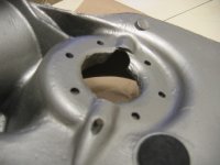
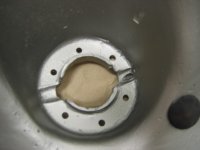
The toughest part though was getting the access hole drilled for adjusting the damping rate on the shocks. The hole is not normal to the surface, so a bit of trickery was involved. I determined where the hole needed to come out by the damper and where it would come out on the other side of the trailing. Using a much smaller drill then my final hole size, I drilled a starter partial through hole that would be removed as it was stepped up in size. The hole was then stepped up in size while "pulling the hole down" by drilling at an angle (yea, yea , I know bad practice to side load the drill but this was an odd situation). By the time it was stepped up to the final size it was a straight shot with a small screwdriver to get the damper adjustment. See attached pictures of drilled trailing arm.
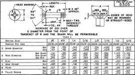
Another suggestion is to use some good hardware. The screws in the hardware for attaching damper brackets to the trailing arm were a 80° included angle countersink and threaded all the way. Given the head thickness with the countersink and the thickness of the bracket pieces with the countersink, they would have stood well proud of the upper surface and if the countersinks were made deep enough to flush mount the heads, it would have knife edged the brackets. I wound up using MS24694 screws (dash number -S103 IIRC which is 1/4"-28, length 1 1/32", grip length 16/32") with a 100° included angle countersink and recut the countersink in the bracket pieces to 100° as well. This pretty much flushed the heads without knife edging the spring pan side of the brackets and the grip length meant that there were no threads to chew away at that relatively soft aluminum trailing arm. You can get these from places like Aircraft Spruce, Pegasus Racing, Coast Fab or even your local aircraft service center. Another option would be to find them under the old part number AN509-416R16.
Attachments
Tybalt
Jedi Warrior
Offline
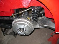
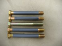
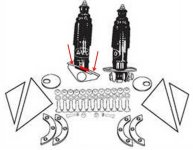
Probably should have tossed in a quick shot of the completed RH Revington kit install less wheel into the earlier post. Also, here are the bolts I used to replace the pivot bolts that came with Richard's adjustable trailing arm brackets. Since those bolts are loaded in shear, I wanted a smooth grip area for the load path. There are definitely cases where Just Say No is appropriate, placing threads in shear is up there toward the top of the list. These are either AN7-40A or AN7-41A (don't recall which was used it was a borderline call) bolts with a quick hit of molybdenum disulfide solid film lube applied. The bolt in the middle is one that came with the brackets. If you elect to use them, the suggestion would be to have the bolt head on the side of the bracket without the adjustment block. The adjustment block will be somewhat more tolerant of the threads being there.
Attachments
Tybalt
Jedi Warrior
Offline
Do you have any idea the thickness of the crescent shaped metal brackets that attach to trailing arm above and below the springpan that the six holes are drilled through. I'm thinking like 1/8".
They are at least .125" but in the back of my mind I seem to recall them being something a little thicker, say .140"(?). It's been several years since I did this and with two shop moves in the interim, I can't find my notebook on all the different things done to car including information on these brackets, D'oh!
Attached is a little bit of a description for the screws used so you can see how grip length vs overall length is defined in the standard. Here's the URL for those screws from Spruce, note that for these screws grip length is overall length less 17/32":
https://www.aircraftspruce.com/catalog/hapages/ms24694.php?clickkey=5737
I used the following types of countersink tools when doing this work:
https://www.aircraftspruce.com/catalog/topages/at442.php?clickkey=16322
https://www.aircraftspruce.com/catalog/topages/at418e-4.php
https://www.aircraftspruce.com/catalog/topages/countersinkcut3.php
What I like about this particular set up is that you can get different sized pilots and diameter cutters, even different angle cutters and play mix and match to suit whatever wild and crazy thing is being done at the time (and trust me on this, we've done all manner of wild and crazy things in the shop). It is a very flexible, but unfortunately pricey system of tools.
If your countersink needs are such that you don't need all that tool system flexibility, these should do the trick and are priced reasonably:
https://www.aircraftspruce.com/catalog/topages/micro-stop.php
https://www.aircraftspruce.com/catalog/topages/stopcountersinkcutters.php (here your cutter is the 12-00947)
It boils down to a judgement call on how many countersinks and the number of different size/angle countersinks you intend to make when selecting the tool system. Another thing is to have a piece of scrap material around so you can set up your countersink depth. Given the bracket thickness, I decided that flush to about .003" protruding head would be the target. This was to make sure that the countersink would not knife edge the bracket and knowing that the slight amount of protrusion would be taken up by the urethane spring pads I was using. It's a trial and error process setting up the countersink depth but once done, you're good until you're either finished with the job or you have change cutters.
Something else that was done was a wet installation of the fasteners and brackets to the trailing arm using a polysulfide sealant. Again Spruce or even places like West Marine carry small quantity containers of polysulfide sealant. You could also use some sort of a chromated primer, but that is getting hard to find now, something about hexavalent chrome compounds and being a carcinogen. Without some sort of wet install, water or water borne solutions can wick their way into the faying surfaces and set up corrosion between the dissimilar metals. This doesn't make that impossible, but does greatly reduce that potential, no pun intended.
Attachments
Tybalt
Jedi Warrior
Offline
Something to keep in mind with these sealants are that they have a working life time that varies depending on the sealant grade you use. Spruce sells the type I've mostly dealt with which are two part mixes, while West Marine sells a single part polysulfide caulk sealant. I have not used the West product before but have friends that have. Since this is not for a fuel boundary, but there for faying surface seal and fastener installation in this application, it may be the easier one to deal with in this situation. When dealing with sealants, it can get messy so wear clothes that you won't mind potentially being ruined as it is easy to get this stuff everywhere and it doesn't come out/off of clothing easily. Take a look at these two links, if you have any questions about the two part stuff from Spruce like what do they mean by "A-1/2 or B-2", shoot me a PM. Since I'm bad about not noticing PM notifications, if you do send a PM, post back here telling me to go check for it.
https://www.westmarine.com/buy/boatlife--polysulfide-life-caulk-sealant-310ml-cartridge--13677679
https://www.aircraftspruce.com/search/search.php?s=POLYSULFIDE+SEALANT&x=0&y=0
https://www.westmarine.com/buy/boatlife--polysulfide-life-caulk-sealant-310ml-cartridge--13677679
https://www.aircraftspruce.com/search/search.php?s=POLYSULFIDE+SEALANT&x=0&y=0
Tybalt
Jedi Warrior
Offline
For sure, the six screws with nuts that hold the inside and outer crescent brackets on the trailing arm, do you know if they are 1/4" or possibly 5/16" counter sunk holes
From post #24 “I wound up using MS24694 screws (dash number -S103 IIRC which is 1/4"-28, length 1 1/32", grip length 16/32") with a 100° included angle countersink and recut the countersink in the bracket pieces to 100° as well.” The information on how the basic dimensions are defined and the dimensions for the nominal size, thread pitch, screw diameter, head dimensions and included angle for the head are shown in the attachment to post #29.
I have sent you a PM, take a look at it and PM back after you've had a chance to work through it.
Foura
Jedi Hopeful
Offline
I have always had a problem with the kits that mount the shock inside the spring. As they are mounted about 2/3 of the way along the trailing arm, they have to be much stiffer to provide the same level of wheel control as the ones mounted behind the axle because of the shorter travel. Neil Revington says that Triumph should have mounted them in this position, yet Triumph mounted the shocks behind the axle on the Stag and the 2000/2500 cars. This is the same position as used by the Moss kit, which also takes the load back to the original lever shock mounts. The concentric shock kits require the drilling of 6 holes in 40-50 year old castings, many of which are already showing signs of stress as seen so often on this list. Then you have to weld strengthening gussets onto the cross member to take the loads from the upper shock mount. Seems like the potential for a few problems.
I had always thought that the longer the travel of the shock absorber, the better.
I had always thought that the longer the travel of the shock absorber, the better.
Tybalt
Jedi Warrior
Offline
Rocky,
I can understand the reservations about making satellite holes in the spring pan of the TR6 trailing arm, it’s a cromulent concern. It’s not uncommon for cracks to initiate and propagate between a primary hole and any surrounding satellite hole. I had the same concern and did a little digging first. I will whole heartedly agree that this system isn't for everyone since it is not a strictly "bolt on" system.
Before pulling the trigger on getting this set up, I asked that a photocopy of the upper portion of the spring pan shock bracket be made and mailed to me. Once that was in hand and compared to its mating surface, that concern pretty much went away. First, I felt that there was sufficient edge distance between the primary hole and where the satellite holes would be drilled. Secondly, while I have been calling these damper mount bits at the trailing arm spring pan brackets, the ones on the top side of the spring pan are really functioning purely as doublers. The lower one is essentially two doublers that are joined together by a pair of lugs welded to each of the doublers for mounting the lower end of the damper in double shear. In the attachment (an edited screen shot from TRF's Green Catalog), you will see a small red rectangle and two red arrows. The rectangle is the gap between the “doubler” portions of the damper lower bracket and the two arrows point to the two doubler segments. They are like the upper spring pan brackets/doublers with the exception of not being counter sunk.
What this effectively meant was that the spring pan was being sandwiched in between two doublers, each of which had raw modulus values approximately three times that of the spring pan itself making that area a good bit stiffer. As far as taking the tensile and compressive loads, there was no information on which specific steel alloy was used nor which specific aluminum casting alloy was used for the trailing arm. Thinking about typically low alloy steels that are easy to work with and can be used in the as welded condition along with typical structural aluminum casting alloys, my guess is that the doublers have tensile and compressive strengths that are at least twice that of the aluminum trailing arm and would not be surprised if the strength ratio was higher than that. As long as you are starting with a trailing arm that is in good shape, my take is that there should be no problem.
I do have one complaint though about the Revington kit and that is with the hardware. Those were some of the cheesiest looking fasteners I think I’ve ever seen. I can be rather retentive when it comes to hardware, but I come by that for cause. Many years ago when I was racing motorcycles, I installed a somewhat cheesy hardware store metric fastener as a placeholder for a critical application. This was decades ago when even finding any kind of metric stuff in a hardware store in this country was tough so I felt a bit lucky that I could even find something that fit. Turned out the replacement fastener did not arrive before the next race, so I off I went and raced anyway. In the second heat, snap, big crash ensues, much pain but fortunately no serious injury, just lots of bumps, bruises, scrapes and a couple of cuts. I’ve been particular about fasteners since that day. The fastener situation for the Revington kit was easily resolved, the stuff from the kit was used as an initial guide, but all fasteners used were either AN or MS or NAS something or another.
Regarding the damper length, I’m of the opinion that damper length is driven by the application. One primary key is getting the damping forces in line with the effective spring rate. As long as the damper’s internal travel is matched to overall suspension travel and damping is matched to the springs, you will have a system that works.
Attachments
Foura
Jedi Hopeful
Offline
I feel your pain after your motorcycle crash! I have never raced my bikes but I did have my little Hodaka Ace 100 seize at 50mph. Scary! I have had a camber bolt fail on my Commodore causing the total collapse of the left front strut. Fortunately, it happened at about 20mph rather than on my normal 70mph freeway commute.
You have obviously put a lot of research and thought into the shock mountings, and I can see how the plates sandwich the trailing arm hole and restore the strength that drilling the new satellite holes might cause. It still seems that the drilling of the holes and the welding of the gussets on the upper mount are things which would be best done by professionals. Despite Neil Revington's claim that Triumph should have mounted the shocks concentrically with the spring, they chose not to do so, starting with the Triumph 2000 in 1963 through to the last Stags in 1978, and including all of the TRs from the 4A to the TR6. I suspect that they did so because mounting the shock behind the axle allowed the fitting of a shock with a much "softer" valving and a larger oil volume than one mounted 2/3 of the way along the arm, and thus subjected to higher leverage forces.
Do we have any shock experts on the list?
This project took longer than i thought,parts shipped in etc ,time for rest for the old guy Casualties included drivers side emergency cable ,passenger side brake line. My neighbour who given the time could easily fix a rainy day, watched me wrestle with removing the bushings . He suggested drilling the middle out with a slightly larger bit than the centre on my drill press. Halfway through it broke free and was pushed out the bottom . The bushing was worked out with a long bladed screwdriver . The passenger side bushings from the time on the bench both sides removed in less than ten minutes I am vacuuming brake lines to-day and plan on a ride in the new week To the eye after rolling up and down the drive , looks 100% better
One side note : a previous owner drilled three new holes in the brackets on the passenger side ,so he was wrestling with camber also
Thanks everyone for the help--- Next on the list is the Main and connecting rod bearings
Terry
One side note : a previous owner drilled three new holes in the brackets on the passenger side ,so he was wrestling with camber also
Thanks everyone for the help--- Next on the list is the Main and connecting rod bearings
Terry