I installed a Nippon Denso alt out of a 95 Corolla on my TR4 and the wiring was fairly simple. I did however omit the ammeter and replaced it with a voltmeter. I wired the alt with the 3 signal control wires, ignition, battery voltage and charge light.
How was the alternator converted? I found this pdf showing internal modifications -
https://www.google.com/url?sa=t&rct...zpm93TOuBs1FFpo9V6c-RWg&bvm=bv.92291466,d.eXY
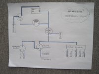
In your diagram the ammeter would go between the battery and ign switch and you may need to install a shunt depending on the electrical loads. Are you planning to run the alternator high current output directly to the battery? That is how I did it with a #8 wire to the starter solenoid.
Is your starter button powered with the ignition off that is how you show it wired? Do you plan on rewiring the car?
The one wire alternator has only the High current wire to the solenoid and is self exciting.
I found this online:1-Wire Explained
A 1-wire alternator, also known as a self-exciting alternator, is commonly used on custom cars & trucks, tractors and other non standard applications when simplified wiring is a factor. As the name implies, these alternators provide only one wire connection: the BATT terminal. A heavy cable is typically run directly from the BATT terminal to the positive terminal of the battery.
1-wire alternators are essentially 3-wire setups that have been rewired internally for a simplified final installation:
•No Remote Voltage Sense Input:
The regulator's sense line is still used, but instead of connecting to a remote location in your car, it is simply routed directly to the output feed of the regulator. This connection may be inside the alternator where it would be completely hidden from view, or the sense line may actually have an external terminal attached to the output feed stud on the back side of the alternator (see photo above).
A common complaint among custom street rod owners using the 1-wire setup is that their headlights are dim, even with a huge 100-amp alternator wired directly to the battery. This is due to the lack of remote voltage sensing at the power distribution point.
•No Field Excite/Warning Light Indicator Input:
The ignition warning light indicator function is omitted with a 1-wire alternator, so your idiot light will not be operational with this setup.
For the 1-wire, self-exciting design, the field windings are not energized via the ignition switch; instead, a special circuit is built into the internal voltage regulator that senses the rotation of the alternator’s rotor. The rotor must turn at sufficient speed to trip the circuit which excites the field windings and starts the charging process. This “cut-in” speed is affected by several things and is typically higher with certain high amperage alternators. Prior to reaching the cut-in speed, the charging system is not activated and the battery will be discharging. However, once the cut-in circuit is tripped, the alternator will charge at all speeds, even very low ones, until the alternator’s rotor comes to a complete stop. At that point, the circuit will shut off and wait for the process to be repeated.
Typically, after starting the engine, the engine must be revved above 1200-2000 RPM to turn-on the 1-wire alternator.
The advantage of a 1-wire system over the 3-wire system is that the installation is simplified and provides for a very clean installation. All that is required is a heavy gauge cable running between the output feed stud on the rear of the alternator and the battery.
Some of the disadvantages associated with the 1-wire system are:
•Less than optimal voltage levels at points downstream from the alternator;
•The ignition warning light is omitted;
•At startup, a slow-running engine will not be spinning fast enough to turn-on the alternator and the system will be discharging until the throttle is blipped and the engine revs higher than the alternator cut-in speed.
•Higher cost than 3-wire equivalent.
Summary:
3-Wire Alternator:
Advantages
•Ignition warning light works as designed.
•Field windings turn on with ignition switch (no cut-in required).
•Much better voltage regulation at the main terminal power post.
•Inexpensive and plentiful.
Disadvantages
•A little more complicated to wire up.
1-Wire Alternator:
Advantages
•Installation is simplified and provides for a very clean setup.
Disadvantages
•Regulated voltage monitored at alternator; low voltage conditions may occur at main terminal power post.
•The ignition warning light is omitted
•Throttle must be blipped 1200-2000 RPM at startup to force it to cut-in.
•More expensive to buy.

 Hey Guest!

 Hey - did you know if you click on the title of a thread it will take you to the first unread post since you last visited that thread?
 but were afraid to ask:
  STOP!! Never post your email address in open forums. Bots can "harvest" your email! If you must share your email use a Private Message or use the
  smilie in place of the real @
 Pretty Please - add it to our Events forum(s) and add to the calendar! >>