• Hi Guest!
    If you appreciate British Car Forum and our 25 years of supporting British car enthusiasts with technical and anicdotal information, collected from our thousands of great members, please support us with a low-cost subscription. You can become a supporting member for less than the dues of most car clubs.

    There are some perks with a member upgrade!
    **Upgrade Now**
    (PS: Subscribers don't see this gawd-aweful banner
Tips
Tips

Fuel Gauge

vette

Darth Vader
Silver
Country flag
Offline
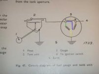
Hello Everyone, I have a guestion on my fuel gauge. I'm checking continuity on all my circuits as I am fusing the new system. With the sending unit wire disconnected and not touching anything, should i be reading continuity to ground from my input wire to the gauge. Some clarification of the circuit is that this particular circuit in my car is wired as in the early 100/6 cars. That is the power source comes from the fuse, then to the fuel gauge, then continues on to the Heater Switch then to the Heater motor. During this test, the heater switch is in the off position. Oh, also the source wire is removed from the fuse box. Thanks, Dave.
 
I'm assuming from your post that your gauge doesn't work and that you have continuity to ground. I had similar problem that drove me nuts until I realized that the power wire was somehow touching ground even though it looked like it was only touching the center post. I loosened the nut securing it slightly, and presto! the gauge began working. I think after that I inserted some fiber washers on the post to improve the insulation from ground, but I can't remember for sure...
 
Thanks Keith. I did alittle more research on the net and found this. It shows that the circuit thru both coils in the fuel gauge does end up attached to ground. Then the sending unit is tapped into the gaugle coils circuit between the two coils. This makes the sending unit parallel to the left hand coil which is called a shunted sending unit. That way you don't send alot of current thru the sending unit which is in the tank and can create heat.
What I am up to is testing each circuit in my new electrical system before I energize it with a fuse. When I read thru this circuit and read to ground I wasn't sure where it was happening. So I was looking for any info I could get. When I found this attached drawing I was pretty sure things were ok and I installed the fuse. Nothing blew up and no smoke escaped and the gauge works so I guess I survived that one. Thanks again. Dave.
 

Attachments

  • fuel gauge.jpg
    fuel gauge.jpg
    5.2 KB · Views: 87
I'm glad I deleted my post because initially I said there shouldn't be a ground, but then I realized there had to be a connection to ground.
 
Thanks Keith. I did alittle more research on the net and found this. It shows that the circuit thru both coils in the fuel gauge does end up attached to ground. Then the sending unit is tapped into the gaugle coils circuit between the two coils. This makes the sending unit parallel to the left hand coil which is called a shunted sending unit. That way you don't send alot of current thru the sending unit which is in the tank and can create heat.
What I am up to is testing each circuit in my new electrical system before I energize it with a fuse. When I read thru this circuit and read to ground I wasn't sure where it was happening. So I was looking for any info I could get. When I found this attached drawing I was pretty sure things were ok and I installed the fuse. Nothing blew up and no smoke escaped and the gauge works so I guess I survived that one. Thanks again. Dave.

Hi Dave,
My understanding of this is that it will be connected to ground through the variable resistor in the sending unit. If your sending unit is reading continuous with ground then it means that the 'hot' wire is connected to ground someplace beside through the resistor. You should be able to measure a resistance change as you move the float lever up and down.
Keith
 
Yeh Tim, that was my position as well. When I had the gauge apart to clean it it had been awhile and I couldn't remember what it looked like. But then I found the schmatic and it showed that the coils do get connected to ground in the gauge to complete the circuit. This is the distinction between a 2-wire gauge circuit and a 3-wire gauge circuit.
Keith, look at the schmatic in my previous post, you will see that in a 3-wire fuel gauge circuit, the sending unit is connected to the guage circuit at the top of the left hand coil and then that coil has a ground connection at the gauge. The sending unit also of course has its ground connection. This puts the sending unit in parallel with the right hand coil. this way the sending unit only has to handle part of the current in the Parallel circuit. In a two wire gauge circuit, all of the current goes thru the sending unit. Because I couldn't remember the internal circuit wiring of the gauge I didn't know if the Healey was a 2-wire or a 3-wire gauge circuit. Thanks you all. Dave.
 
Back
Top