• Hi Guest!
    If you appreciate British Car Forum and our 25 years of supporting British car enthusiasts with technical and anicdotal information, collected from our thousands of great members, please support us with a low-cost subscription. You can become a supporting member for less than the dues of most car clubs.

    There are some perks with a member upgrade!
    **Upgrade Now**
    (PS: Subscribers don't see this gawd-aweful banner
Tips
Tips

Seat sliders

Jeepster

Jedi Trainee
Country flag
Offline
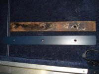
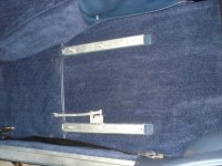
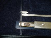
I am in the process of restoring the seat slider mechanisms. They are in a pretty bad state, seized with missing studs etc.
Would anyone have a picture of what a good condition set should look like? I have no idea what length the studs should be ?

Also, what order do the sliders and associated parts fit in the car? Is it seat then sliders then wooden packing piece? The parts suppliers show a tube nut, does this fix the slider to the floor or seat to the slider?
 
Good questions - I'd like to know the answers t these too!
 
I cant speak for Jeepster, but I'm interested in their smooth functioning...
 
Tube nuts come up through the floor from underneath. They have a thick washer and spring washer as well. Inside there is the metal reinforcing plate on top of the underfelt/tar paper, then the wood, then the seat slider with the narrower part facing down. The carpet is cut to fit around the wood strips. The seat frame goes on last with regular nuts and plain washers which stick up into holes cut in the wood seat bases when they are put in.

Studs are fairly easy to replace, just find appropriate length bolts and cut the heads off. Drill and tap the broken off studs to accept the cut-off bolts and fuse them in with a TIG welder on the opposite side. You can't just thread bolts in as the heads get in the way of the slider.

I don't have measurements of the studs but the top ones have 14 threads visible and the bottom ones have 20 threads visible.

Andy.
 
No wonder mine don't look like good engineering.. I'm missing the tube nut/reinforcing place set on the passenger seat and the nut/reinforcing plate/wood on the driver... very agricultural fitting by the PO :sour:
 
Andy

What do the reinforcing plates look like - Moss, AH Spares, and Ahead4Healeys dont show them in their catalogs?

Simon
 
The reinforcing plates are heavy sheet metal - maybe 1/16" thick approximately the same size as the wood packing strips.

I elected to put the wood packings on top of the carpet without cutting holes. This makes it harder to remove the carpet under the seats, but easier to slide the seats.

Also - replacement seat mechanisms are not particularly expensive - you may want to just get new ones.
 
Kilmartins have the metal plates which are cut from pre-zinc'd plate and therefore have plain steel edges which may stain the carpet unless painted. There is an austinhealeywood.com website that has the wooden bits or they are pretty easy to make.

I have also put the wood on top of the carpet for now, the intention is to let it compress down and mark the perfect outline for cutting later on.

Andy.
 
I used aluminum for my metal strips and painted them a dark blue to blend with the carpet. I put the wood directly on the sound deadening and cut the carpet to go around them. I then put the metal strips on top so they prevent the carpet coming up into the sliders.
 

Attachments

  • 2013-02-05 001.jpg
    2013-02-05 001.jpg
    96.8 KB · Views: 117
  • 2013-02-05 003.jpg
    2013-02-05 003.jpg
    95.9 KB · Views: 113
I have only a few ball bearings in my sliders, I think 6 in total on each runner they are not loaded up at all. I think that this is correct. I also got away with using a bolt to replace the missing floor stud, I think that I ground the head down a bit to ensure that there was no clash.

:cheers:

Bob
 
I cannot recall the layering at the moment (wood, sliders, etc.), but since you mentioned about restoring your sliders, the following is a sketch I prepared some time ago before restoring my original Healey's sliders, themselves.

Of course, you can buy new ones, or salvage your old ones.

On salvaging your existing ones, as a recommendation and assuming yours are as in bad of shape as mine were, there is what I referred to and sketched as the "slide stop" (angled as shown). Cut that piece out in its entirety using a dremmel with a cutoff wheel. Note here there is a stud found below the angled stop. If that stud is bad, then this is another reason to cut out the angled stop. You will to replace that and maybe others.

Moving forward, make sure not to scar or cut the main framing surround, especially where the holes occurs. You will need to reinsert a new piece of piano wire or of similar strength and then solder, making sure the rod exceeds enough to prevetn the bearings from rolling out. In other words, replicate exactly the dimensions of the rod and its placement (take pictures of before for record, if necessary). After cutting with the dremmel, the remaining portions of the diagonal rod should slide out. If not, then you will need to ground around the surround in order to remove excess solder. Take note where the bearings and sliding pieces go before disassembling. Wiring brush every movable and nonmovable part, clean, regrease, then re spray. It does take time and effort, but mine looked just awesome when finished.


IMAG0400.jpg
 
I cannot recall the layering at the moment (wood, sliders, etc.), but since you mentioned about restoring your sliders, the following is a sketch I prepared some time ago before restoring my original Healey's sliders, themselves.

Of course, you can buy new ones, or salvage your old ones.

On salvaging your existing ones, as a recommendation and assuming yours are as in bad of shape as mine were, there is what I referred to and sketched as the "slide stop" (angled as shown). Cut that piece out in its entirety using a dremmel with a cutoff wheel. Note here there is a stud found below the angled stop. If that stud is bad, then this is another reason to cut out the angled stop. You will to replace that and maybe others.

Moving forward, make sure not to scar or cut the main framing surround, especially where the holes occurs. You will need to reinsert a new piece of piano wire or of similar strength and then solder, making sure the rod exceeds enough to prevetn the bearings from rolling out. In other words, replicate exactly the dimensions of the rod and its placement (take pictures of before for record, if necessary). After cutting with the dremmel, the remaining portions of the diagonal rod should slide out. If not, then you will need to ground around the surround in order to remove excess solder. Take note where the bearings and sliding pieces go before disassembling. Wiring brush every movable and nonmovable part, clean, regrease, then re spray. It does take time and effort, but mine looked just awesome when finished.


View attachment 27039
I completely dismantled my original sliders and had them CAD plated. If I had to do it again I would not have removed the rivets because they were a real problem to find. AHead4 Healeys had them. I also purchased reinforcing plates from Tom's Imports and they were powder coated black and a first class job. Tom's also has aluminum plates to replce the original wood ones...another "no brainer" choice. You can spend a lot of time on trying to restore the seat tracks so consider that. New tracks have chrome plated handles...another plus for them.
 
Good advice and source info, Patrick.

One bad habit I have is I don't always record every single detail in my sketches and notes when, in this case, restoring my sliders. Case in point, I know I had a bad stud so I took a simple bolt (with matching screw threads) and grinded down the head so it now became a rivet, and then welded that to the track. Yes, it can take time restoring these and might make sense to simply buy new ones. As an alternative, if one has plenty of time on their hands or has limited finances, this is an approach to solving.
 
I changed the mounting studs on the new Moss repro sliders because I needed longer lengths due to my added layers of heat/sound deaden-er, and did not grind the heads but simply tack welded them in place. There is plenty of clearance between the slides for the bolt head. The original studs were just bolts tacked in place anyways. The pins on both ends that act as stops were simply pressed in on the repros, and had knurling on one side to grip the track. I don't recall the original design or not, but the repros were fairly simple to dis-assemble and modify and re-assemble (about 20 minutes each).
JIM
 

Attachments

  • 2013-02-05 005.jpg
    2013-02-05 005.jpg
    96.9 KB · Views: 92
Back
Top