• Hi Guest!
    You can help ensure that British Car Forum (BCF) continues to provide a great place to engage in the British car hobby! If you find BCF a beneficial community, please consider supporting our efforts with a subscription.

    There are some perks with a member upgrade!
    **Upgrade Now**
    (PS: Subscribers don't see this gawd-aweful banner
Tips
Tips

Healey assembly line - engine installation

Lin

Jedi Knight
Gold
Country flag
Offline
As I am sure many of you did, I enjoyed reading "A visit to the MG Austin-Healey factory at Abingdon, June 1967" by James Blohm in the latest issue of The Healey Marque.

Those who have restored their cars or pulled and replaced their engines have often wondered how much of the complete engine assembly can I "drop-in" the engine bay with an engine hoist. The subject has also been discussed here before. Of course, there is always a difference between "how much can I drop-in from above" versus "how much do I want to drop-in from above?" Fresh paint tends to make us all cautious.

I have seen factory assembly line photos before, but the one in the article referenced above is one of the better ones I have seen. I would be curious what others of you observe and think. One cannot see the left side of the engine in the photo, but it is clear that the inlet manifold and carbs, sans air cleaners, are mounted on the engine. The right side of the engine is clearer showing the dynamo, coil, distributor, ignition wiring, fan and fan belt, starter and RH motor mount. I think the vacuum line from carb to distributor is also in view? We cannot tell if the LH motor mount is on the engine or not. I would assume that the exhaust manifolds are mounted but one cannot tell for sure from the photo. Clearly the exhaust downpipes would have to wait until the engine was in the car.

What are your conclusions? Interesting that the two motors showing the radiator fans have the fans in identical positions. I don't see the radiator poking its head tank above the front lip of the shroud, so as I would expect it was probably inserted later in the process. It is hard to tell in the photo but it looks like the coolant hoses to/from the radiator are not installed on the engine.

Again, curious about your observations.

Lin
BJ8 Assembly Line 1967.jpg
 
Hello Lin, I agree with your assessment. One thing of note that I think I’m seeing is the attaching mechanism for the engine hoist. It appears different than anything I have seen before and different than the recommended lift points in the owners booklet and the shop manual. The mechanism shown here appears to have claw like appendages grabbing around either the base of the head or grabbing into the recessed area of the spark plugs. ( I can’t see the pic with my iPhone right now). I wonder if the position of the fans is just a result of the way the line worker conveniently grab the blades and bolt them up. With the belt tightened they then would not move easily.
 
Also, I didn’t mention that I was always concerned about picking up the engine and the trans together by the proscribed method in the manual. The engine & trans w/OD all connected together weigh about 720 lbs. Picking that weight up by just the two valve cover studs scared the begeezes out of me. I then devised my own way ( of course ) and attached chains to head bolts on the left side of the head the right side chain end were bolted to ā€œearsā€ on the front and back engine plates. At a later time I happen to send a picture of that arrangement down to Bruce Phillips at Healey Surgeons. I got an e-mail back that said that is definitely NOT the way to pick up that engine and assembly. He said I would break the ā€œearsā€ off of the end plates. Well the job was done, everything back in the car, nothing broken so it was too late to change my ways.
 
The other unusual area of the engine attachment device is the wheel with 5 holes on the front of the beam. Looks like it could be used to rotate the engine side to side when dropping it in the bonnet opening.
My engine has been removed and installed 3 times since new. First two times through the bonnet opening. Last time directly to the frame with no body panels attached. The last time was certainly much less stressful.
My guess is that it moves crane attachment point front and back to tilt the engine. The wheel probably rotates a screw inside the beam. Mine does that, except I have a crank instead of a wheel.
 
John, I think you are correct. I imagine the guy who was assigned that job got pretty good at spinning that wheel just the right amount to stab the unit in the opening.
Also, all the other photos in John Blohm's wonderful article were in color. I'll bet shot on 35MM Kodachrome film. The only B and W shot in the article was copied from a Road and Track magazine.
 
I'm guessing they pull the bonnet off right before they install the engine. It's attached to the car when the body was assembled at the Jensen factory and later shipped to Abingdon for completion. At least that seems to make sense.
 
Last edited:
My guess is that it moves crane attachment point front and back to tilt the engine. The wheel probably rotates a screw inside the beam. Mine does that, except I have a crank instead of a wheel.
I was thinking the same thing about the adjustable lift point. If you look closely, the wheel does appear to have a handle on it at the bottom.
 
On a somewhat related note, am I the only one who thought the photos looked colorized (Photoshop)?

"Colorized" normally refers to adding color to an original that is black and white. Not sure that's what you meant, but the images were originally color images. I believe they were transparencies ("slides") that were scanned and submitted to me as jpegs.

You mentioned Photoshop. I put every image that goes into Healey Marque magazine through a 20- to 25-step process ("work flow"). I do most of the processing in Adobe Bridge, but I finish-up in Photoshop. I rarely, but occasionally, also use Silver Efex Pro 2 and a couple others, but Bridge is the main tool with Photoshop for some finishing touches.
 
On a somewhat related note, am I the only one who thought the photos looked colorized (Photoshop)?

For point of comparison, this is the original jpeg that Jim Blohm submitted to Reid and me along with his article from his original slides. I'm guessing Kodachrome as well, as Paul Simon once said "They give us those nice bright colors" For all the griping we do about social media, it has really brought the Healey world closer and unearthed scores of stories that wouldn't have been shared otherwise. I spotted Jim's photos on a Healey Facebook page and asked him if he would do an article for the Healey Marque to which he graciously agreed and turned out this real inside look at how our cars were built.

thumbnail.jpg
 
That is a great photo! Thanks for sharing. Since I love Healey history any chance of putting up some additional photos of the factory? TIA!
 
That is a great photo! Thanks for sharing. Since I love Healey history any chance of putting up some additional photos of the factory? TIA!

Scot, this is your lucky day! Memberships in the Austin-Healey Club of America are still available, and here's the kicker: With that membership you get Healey Marque magazine! Act now and you can still make the deadline for the 2020 Membership Directory, bringing you contact info for all 47 chapters and their 3,000 members. Operators are standing by!

 
The body number is stamped on one of the hood hinges, and the hood latch as well as the batch/body plate so they can reunite the correct hood with the body.

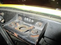
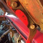
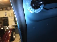
For BJ8s, it was not the body number stamped on the bonnet latch, bonnet hinge flange, and boot lid prop rod attach tab but a number not related to identity of the car. It was a letter, followed by one, two, or three numerical digits. I posted a request on this forum several months ago for Healey owners (all, not just BJ8) to send me those numbers from their car to support a study of them I was (and still am) doing. I got exactly TWO responses.
 

Attachments

  • 36666 - bonnet latch (P429).jpg
    36666 - bonnet latch (P429).jpg
    119.3 KB · Views: 136
  • 28017 (G638).jpg
    28017 (G638).jpg
    127.4 KB · Views: 132
  • 39629 - boot lid (C104 - not original).jpg
    39629 - boot lid (C104 - not original).jpg
    84 KB · Views: 133
Back
Top