• The Roadster Factory Recovery Fund - Friends, as you may have heard, The Roadster Factory, a respected British Car Parts business in PA, suffered a total loss in a fire on Christmas Day. Read about it, discuss or ask questions >> HERE. The Triumph Register of America is sponsoring a fund raiser to help TRF get back on their feet. If you can help, vist >> their GoFundMe page.
  • Hey there Guest!
    If you enjoy BCF and find our forum a useful resource, if you appreciate not having ads pop up all over the place and you want to ensure we can stay online - Please consider supporting with an "optional" low-cost annual subscription.
    **Upgrade Now**
    (PS: Subscribers don't see this UGLY banner)
Tips
Tips

TR2/3/3A Electrical Wiring Best Practices

DornTRoriginal

Jedi Hopeful
Gold
Country flag
Offline
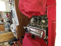
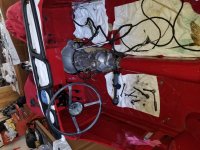
I am moving on to installing heater steering wheel wiring harness and the electrical system, of course there are questions. I have looked over past posts and found some great information, unfortunately I lost the threads with posts and pics from Randall and Geo regarding the use of a small resistors? behind gauges which I would like to see those again as I think these were good additions and would be worth doing if you guys would not mind re-sharing? Sadly this has been a wild journey, I bought the cloth wiring harness from TRF in 1993 (and now it's going in the car yea!), gear reduction starter (2010), alternator conversion kit from Moss (2013) and the gauges have all been restored by Palo Alto Speedometer (2014), an aluminum low profile Fan (12V) Radiator from Wizard Cooling (2012) with relay and wiring harness, now it time to get it done. Presently I am debating the order in which to proceed with installing the dash, heater, wiring and other bits and wondering how it all fits together AND HOPEFULLY I don't need to buy too much more stuff at this point.

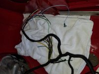
What are your suggestions, recommendations and "best practices" for putting all this stuff neatly and safely into the car? Any pictures of installations is welcomed too! Where and what is the connector on the blue wire in the third picture?

I appreciate your input!
Dash (1).jpgDash (2).jpgWiring Harness.jpg
 

groupdeville

Jedi Hopeful
Country flag
Offline
Old race car trick: Paint the underside of the cowling bright white. The extra reflectance up under there will assist in seeing what you're doing both at the time of the initial wiring/component install and at the time of repair or replacement work later on.
 

Geo Hahn

Yoda
Country flag
Offline
Everyone will approach this there own way. I had lots of time as the car was in the paint & body for more than a year so I documented the harness I was going to use.

Yeah, I had a wiring diagram and notes on what I had removed (a mess) but this book showed exactly what was in the harness I bought and where it would be connected.

J5lP9Pu.jpg


Every wire and its connector were accounted for, line by line. I also made a diagram of the physical layout of the harness (had it spread out on the floor, resisted the urge to sit in the 'driver's seat' and make motor noises):

7BRL6o2.jpg


Methodical to the point of OCD, but like I said - I had the time. When the actual install came around it only took a few hours and everything worked the first time.

I do not recall offhand if your TR uses Lucar (spade) connectors or clamping screws to make the connections. Mine was the latter and I use a bit of solder on the tip of each stripped end. Just a bit on the end to limit fraying but not so much as to create a brittle section at the connection.

BTW my chart shows the solid blue wire goes to the dipper switch (top of left hand page, 1st photo). The one to the light in the speedo is a blue/white (and has a socket on the end).
 

charleyf

Luke Skywalker
Country flag
Offline
One method of sorting out all the wires and where they go is to get a variety of color coded plastic ties. I layed out the harness and Using the wiring chart locate each wire and what it goes to. Place a matching color coded tie on each of those. Then when you start installing each item you can look for the colored tie that matches the place you are working on. This is lot less confusing than continually referring to the wiring chart.
 

TR3driver

Great Pumpkin - R.I.P
Offline
unfortunately I lost the threads with posts and pics from Randall and Geo regarding the use of a small resistors? behind gauges which I would like to see those again as I think these were good additions and would be worth doing if you guys would not mind re-sharing?
I'm not quite certain what you are asking about here. Perhaps the ammeter shunt so you can use the stock ammeter with an alternator (without tearing it up) ?

Otherwise, my only resistors are in the relay circuit to make the rear corner lamps serve triple duty (turn/stop/tail); the fan controller, and the LED lights in the rear.
 

CJD

Yoda
Country flag
Online
I'm not quite certain what you are asking about here. Perhaps the ammeter shunt so you can use the stock ammeter with an alternator (without tearing it up) ?

Otherwise, my only resistors are in the relay circuit to make the rear corner lamps serve triple duty (turn/stop/tail); the fan controller, and the LED lights in the rear.

I think he is probably referring to the OD solenoid diode.
 
OP
DornTRoriginal

DornTRoriginal

Jedi Hopeful
Gold
Country flag
Offline
I'm not quite certain what you are asking about here. Perhaps the ammeter shunt so you can use the stock ammeter with an alternator (without tearing it up) ?

Otherwise, my only resistors are in the relay circuit to make the rear corner lamps serve triple duty (turn/stop/tail); the fan controller, and the LED lights in the rear.

What I recall was a small, liner looking thing that had to be installed correctly, one way for positive ground opposite for negative ground, and I think it was to protect the instruments, amp gauge, maybe I am delusional? The suggestion to use an ammeter shunt is interesting, I am using the stock amp meter, ummm anyone installed it? I am thinking the AMP gauge is not going to work the way it did with the generator and I am not sure where I should put the field/instrument wire from the alternator, the Moss how to video indicates it should go to the instrument panel light but TR3s don't have those? The AMP meter seems to be the logical spot. One side of the Amp meter to the alternator the other side to the (negative side) of the Battery? Eliminating all the wires to the regulator but still going to the fuses correct?

Does anyone have a good picture of which holes in the fire wall the wires are to be routed into the engine bay?
 

TR3driver

Great Pumpkin - R.I.P
Offline
What I recall was a small, liner looking thing that had to be installed correctly, one way for positive ground opposite for negative ground, and I think it was to protect the instruments, amp gauge, maybe I am delusional?
Ah, that would be the diode I added to the OD relay. It helps replacement relays last longer. My original relay went roughly 40 years, but I was having a real problem with replacements failing in just a few months until adding the diode.
The suggestion to use an ammeter shunt is interesting, I am using the stock amp meter, ummm anyone installed it?
I used the stock ammeter with a 60 amp alternator on my previous TR3A for roughly 30 years; worked fine once I added the shunt. Without the shunt, the ammeter needle would bang against the peg at every cold start, which appeared to be slowly damaging the ammeter movement. The needle started sticking against the peg, and wouldn't drop unless I thumped the meter or hit a bump. But with the shunt, it continued working normally and was still doing so when the car got wrecked.

More recently, I put a ~50 amp alternator on my current TR3 (smaller housing, fits much better than the previous one) and saw the same thing.
https://imgur.com/X4GAP8v

I am thinking the AMP gauge is not going to work the way it did with the generator
It can, depending on how you connect the alternator. Many people (including Dan Masters, not sure about Moss) have suggested connecting the alternator so it's output does not pass through the ammeter. That means the ammeter will always show discharge even when the battery is being charged. I like having a functional ammeter, so I went the other way.

and I am not sure where I should put the field/instrument wire from the alternator, the Moss how to video indicates it should go to the instrument panel light but TR3s don't have those?
Sorry, I'm confused again, perhaps partly because I'm not familiar with the Moss video. The 'I' (or in some cases 'L') terminal on the alternator is for the "ignition" warning light on the dash. It must not be connected anywhere else. If you aren't using the warning light, you can either leave it disconnected, or connect a dummy load from it to the ignition circuit. Alternators without a field input (like the Ford Motorcraft I used before) sometimes rely on the current through the lamp to help them get started without having to rev the engine up.

Some alternators include a separate input for field power, which needs to come from a switched power source. On my Denso, it was labeled 'IG' (for ignition) and I wired it to the fuse block (along with the white wire from the ignition switch). Many American alternators don't have this input.

Some alternators include another "sense" input, which should be connected as close to the battery as practical. Labelled 'S' on my Denso, I wired it to the starter solenoid.

Here is a diagram that summarizes the connections
7NFeNDf.jpg

Eliminating all the wires to the regulator but still going to the fuses correct?
Up to you. I used the original control box as a junction block, a convenient place to join the harness wires together with the wires from the alternator. But it serves no other purpose, so can be eliminated if you prefer.

https://imgur.com/Iy4cOxM
 
OP
DornTRoriginal

DornTRoriginal

Jedi Hopeful
Gold
Country flag
Offline
Great Information! Thanks Randall! I think I will try using the old reg box, shunt, relay for fan and wire the starter motor so the starter is powered but there is still the use of the original solenoid, I believe that is similar to what you did, I like it! This electrical part I am finding a bit of a challenge, I accumulated stuff over time without knowing how to install them & then things went weird, too much elapsed time has gone by, now I am trying to put it all together. The alternator I have is a 45 amp and I have converted the pulley and belt so now it just a matter of getting all the wires in the right locations. LED lights are starting to be a consideration too.

Thanks everyone for the help I don't know how I'd get this task completed without everyone's input and the ability to wine every now and then! Mahalo!
 
OP
DornTRoriginal

DornTRoriginal

Jedi Hopeful
Gold
Country flag
Offline
Methodical to the point of OCD, but like I said - I had the time. When the actual install came around it only took a few hours and everything worked the first time.

I wish I had used a notebook I used little sticky tabs on each wire after 20 plus years they fell off..... go figure!
 
Similar threads
Thread starter Title Forum Replies Date
Got_All_4 TR5/TR250 Wiring/Electrical Mystery Worked Perfect Then Not Triumph 5
B Bugeye Electrical Wiring Diagram in Logic Format Spridgets 17
H Re: electrical short wiring damage Spridgets 11
S TR4/4A Electrical wiring tips Triumph 2
KVH TR4/4A Stumped on Electrical Wiring--TR4A Triumph 7
B 59 electrical wiring Triumph 2
77MidgetMkIV question on electrical gauge wiring Spridgets 14
CARSINC Sprite Electrical System Information Spridgets 2
K TR2/3/3A Turn signal flasher issue.....electrical is not my strong point. Triumph 13
R Electrical Experts - Vixen 2500 - Ignition Switch Observation? TVR 10
N MGB Electrical Part Identification MG 3
KVH General Tech Yes, the Horns Again--Electrical TR4A Triumph 8
SNClocks Electrical Wire Lug Spridgets 2
K TR2/3/3A Another electrical problem: Park light & 5ignal light on Drivers side are brighter than....... Triumph 3
F General TR Electrical parts Triumph 6
S TR2/3/3A Electrical Triumph 31
lram59 General Tech Electrical terminals Triumph 8
6 Electrical Help Please Spridgets 7
B Bugeye Electrical Diagram with additions Spridgets 6
B Austin-Healey late 3000 BJ8 Electrical Diagram Austin Healey 1
B Austin-Healey early 3000 BJ8 Electrical Diagram Austin Healey 0
B Austin-Healey 100-6/3000 Electrical Drawing Austin Healey 2
B Austin-Healey 100 BN2 Electrical Diagram Austin Healey 0
B Austin-Healey 100 BN1 Electrical Diagram Austin Healey 0
KVH General Tech O/D Electrical Wire Burned Triumph 22
J TR4/4A Getting electrical shock from horn button when using the horn. Triumph 9
E GT6 Help electrical guru needed Triumph 4
B Bugeye Electrical Diagram Spridgets 0
D TR2/3/3A TR3A electrical issues Triumph 2
dbenichou289 TR2/3/3A Heater electrical connections Triumph 4
Simmo General Tech Electrical question Triumph 4
B BJ8 Phase 1 Electrical Diagram Austin Healey 21
T TR6 72 TR6 electrical snafu Triumph 4
P TR6 Electrical Problem Triumph 26
M Difficult Electrical Problem in 59 BE with Generator Spridgets 6
N Electrical Issues Need Help Austin Healey 8
I Bugeye electrical questions Spridgets 17
N Electrical Troubleshooting Advice Needed Spridgets 6
steveg Electrical sleeving Austin Healey 11
N TR6 Electrical Issues Triumph 5
N Electrical issue. FORUM Navigation Questions 2
C Ghost in the electrical system Austin Healey 51
S TR2/3/3A Electrical Issue Triumph 40
KVH General TR Steering Shaft/Column Short Circuit?--Electrical Issue with Light Switch Triumph 3
6inline Electrical gremlins giving me fits Austin Healey 18
R TR2/3/3A Early TR3 electrical system Triumph 12
K TR2/3/3A More electrical....the Starter? Triumph 8
K TR2/3/3A More electrical....the Starter? Triumph 5
B TR2/3/3A Electrical Problem Triumph 13
T TR2/3/3A electrical oddity Triumph 7

Similar threads

Top