• Hi Guest!
    You can help ensure that British Car Forum (BCF) continues to provide a great place to engage in the British car hobby! If you find BCF a beneficial community, please consider supporting our efforts with a subscription.

    There are some perks with a member upgrade!
    **Upgrade Now**
    (PS: Subscribers don't see this gawd-aweful banner
Tips
Tips

BJ8 brake connectors

Country flag
Offline
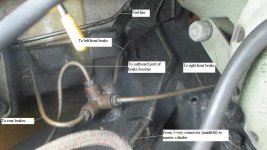
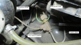
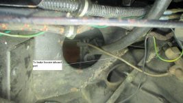
Running all new brakes lines on the 67 BJ8, they were all removed on car when I got it. I 've figured out most of it except for the three way connector from master cylinder to servo. I have the four way in place. Could someone please post picture of it or tell me where where it goes.

Marv
 
Marv, perhaps these photos will help.
 

Attachments

  • IMG_2579.jpg
    IMG_2579.jpg
    50 KB · Views: 177
  • IMG_2580.jpg
    IMG_2580.jpg
    47.9 KB · Views: 172
  • IMG_2581.jpg
    IMG_2581.jpg
    48 KB · Views: 163
Steve,
that helps a lot! Still need to locate three way connector mount hole but your pictures explained a couple of things. Won't get to work on it tomorrow, Honey Doos. Thx,
Marv
 
Three way mounts on the rear axle its fed from the front and splits to do the rear wheels . There should be an L tab on the top/front of the rear axle passenger side between the pumpkin opening and the hub end .Centre of the pic behind the fuel pump .
 
Steve,
looked at the same Moss schematic last night. The three way by number 62 is the one I need to locate its mounting spot. It will be fun to shape and fix the steel line to it. The servo still has it lines on it so will help me locate three way mounting spot. Thx,
Marv
 
Marv, do you not have the hole and the welded-on nut on the back curve of the inner fender well? That's where the 3-way attaches.
 
Marv, do you not have the hole and the welded-on nut on the back curve of the inner fender well? That's where the 3-way attaches.

Yeah as shown installed in your Picture #IMG_2580.jpg
 
A couple more views on a BJ8; your wording threw me off a bit, as the line from the M/C goes directly to the servo, then from the servo to the 3-way adapter (sole purpose to give a port for the brake-light switch) then on to the 4-way, splitting the output from the servo to the individual front brakes and the line running to the rear (and another 3-way adapter).

IMG_2475.jpg


IMG_2477.jpg


4-way, line to rear not yet fitted

IMG_2476.jpg
 
......as the line from the M/C goes directly to the servo, then from the servo to the 3-way adapter (sole purpose to give a port for the brake-light switch)

Randy, on my BJ8 (which has original lines), the line from the master cylinder does not go direct to the servo, but first to the 3-way manifold and then to the servo as shown in my photos IMG_2579 and _2580 above. Am I misunderstanding your statement? Hydraulically, it makes no difference, but physically it does.
 
Randy, on my BJ8 (which has original lines), the line from the master cylinder does not go direct to the servo, but first to the 3-way manifold and then to the servo as shown in my photos
Mine followed that plumbing route too.

Hydraulically, it makes no difference, but physically it does.
Maybe it does make a difference? The brake light switch would be receiving boosted pressure if it was downstream.
 
Thanks Randy. Think I can run with it now. The pictures Steve posted were good but the angle they were taken from was a little confusing to me. On the four way connector, I have mine started with the body to the front where the one in the picture show body to the back. Only have the rear brake line installed so I will be flipping that tomorrow. Thanks again to all!
Marv
 
Mine followed that plumbing route too.


Maybe it does make a difference? The brake light switch would be receiving boosted pressure if it was downstream.

Well, I was thinking more of hydraulic flow than pressure, and the configuration of the lines required to connect one way would be different from the configuration required to connect the other way. If the configuration of my car is original (and it is), then the pressure switch is designed to operate on the lower input pressure from the master cylinder. It would also work on the higher pressure from the servo, but it wouldn't work any better.

The perspective of the photos I posted is necessarily looking down on the passenger's side inner fender while standing beside the car since my engine is installed.
 
Randy, on my BJ8 (which has original lines), the line from the master cylinder does not go direct to the servo, but first to the 3-way manifold and then to the servo as shown in my photos IMG_2579 and _2580 above. Am I misunderstanding your statement? Hydraulically, it makes no difference, but physically it does.

Mine followed that plumbing route too.


Maybe it does make a difference? The brake light switch would be receiving boosted pressure if it was downstream.
I plead the Fifth Amendment...

Now I AM confused; the servo has to have a (hydraulic) pressure inlet, and a boosted outlet, so does the outlet pipe run directly to the 4-way block above the front XMBR? I suppose that routing orientation would render the individual pipe lengths/shapes more manageable in the confines of a populated engine compartment.

I will defer to you guys, as I haven't had a BJ8 in the garage to compare since the one in those pictures left for Albuquerque. At least Marvin could see where the block's mounted (and given that I was working with a set of pre-bent tubes from Classic Tube, I won't be losing any sleep wondering if I installed them right__with the exception of straightening out the big U-bend in the line going to the read, they fit quite well, with only some minor tweaking)!
 
I plead the Fifth Amendment...

Now I AM confused; the servo has to have a (hydraulic) pressure inlet, and a boosted outlet, so does the outlet pipe run directly to the 4-way block above the front XMBR? I suppose that routing orientation would render the individual pipe lengths/shapes more manageable in the confines of a populated engine compartment.

Yes the outlet pipe from the servo goes directly to the 4-way block. From the block, one pipe goes to the right front brake, one goes to the left front brake, and the third goes to the rear brakes.
 
the pressure switch is designed to operate on the lower input pressure from the master cylinder. It would also work on the higher pressure from the servo, but it wouldn't work any better.
Unless it isn't rated for the higher pressure. It is the same part number for all Healeys, servoed or not. The factory may have plumbed it this way to avoid sourcing a more expensive part. Pure speculation on my part here.
 
Got to work on the brake lines yesterday. Had to go buy another 25 ft roll of line. I would have thought 25 ft would have been enough to do car and have some left over. Here's a picture of what I did. Haven't installed the line clips yet.
Marvimage.jpg
 
Back
Top