• The Roadster Factory Recovery Fund - Friends, as you may have heard, The Roadster Factory, a respected British Car Parts business in PA, suffered a total loss in a fire on Christmas Day. Read about it, discuss or ask questions >> HERE. The Triumph Register of America is sponsoring a fund raiser to help TRF get back on their feet. If you can help, vist >> their GoFundMe page.
  • Hey there Guest!
    If you enjoy BCF and find our forum a useful resource, if you appreciate not having ads pop up all over the place and you want to ensure we can stay online - Please consider supporting with an "optional" low-cost annual subscription.
    **Upgrade Now**
    (PS: Subscribers don't see this UGLY banner)
Tips
Tips

TR4/4A TR4A alternator conversion wiring question

tdskip

Yoda
Country flag
Offline
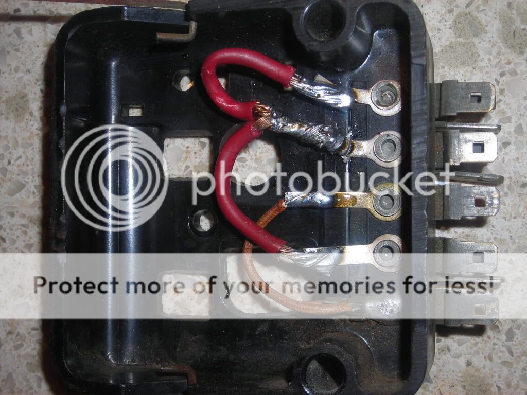
Hi guys - pushing through some wiring issues to get her ready to run. I'm doing an alternator conversion and have a question about where the brown/green wire connects.

The very good Hill County Triumph club write up ( https://www.hillcountrytriumphclub.org/tech-talk/alternator_conversions.html ) says;

"Connect the Brown/Green wire to the plug wire going to the # 1 terminal, using a butt connector, or splice, solder, and insulate with heat shrink tubing."

My question is if "A" is #1 or if "B" is #1 as referenced above

Tr4aIRSalternatorconverstion12-17-10-1.jpg


Thanks!
 

TR4nut

Yoda
Country flag
Offline
Tom-

If you don't see any numbers on the alternator case, do you see letters like S for Sense, and I for Indicator? I believe B is Terminal 1, or the Indicator terminal, and is typically the black wire on the pigtail that plugs into it. A is Terminal 2, or the Sense terminal, and would be red on the pigtail. But someone needs to confirm as I'm not looking at my own car for reference.

Randy
 

martx-5

Yoda
Country flag
Offline
"B" is terminal #1, and "A" is #2. Terminal #1 goes to the dash indicator light, and terminal #2 is the sense wire. That normally would goes to a B+ close to the battery or a major B+ connection point. Most guys however just hook it up to the output terminal of the alternator. The idea of a sense terminal is to take into account any voltage drops from the alternator output to the battery, and then adjust alternator output accordingly.

Here is a link that has a 10 SI wiring diagram that may help. It shows the sense terminal hooked in close to the battery, and further explains all of the terminals.
 

TR3driver

Great Pumpkin - R.I.P
Offline
:iagree:
Just for clarity, Dan's procedure uses the brown/green wire for the line to the dash lamp (originally it was for the field connection to the control box).
 
OP
T

tdskip

Yoda
Country flag
Offline
Specifically - how did you approach joining all of these? Is there a way to do it so that is reversible? Where did leave the wiring afterward?

Larger Brown/Yellow and Brown/White and both Brown/Blue: "

Using a large, solder type butt connector, connect all 4 of these wires together, and insulate with heat shrink tubing. Be aware - this connection carries ALL of the current for the car, so it must be a good connection. You do not want a high resistance here. You may have to go to an electrical supply house for this type connector, rather than an auto supply store, to get one large enough to hold all 4 wires. Run two wires into one end of the connector, and the other two into the other end."
 

TR3driver

Great Pumpkin - R.I.P
Offline
My TR3 had the screw-type control box, so originally I just added the output wire from the alternator to the A terminal. But eventually the A-A1 connection inside the box opened up. Left me in kind of a bind (car wouldn't start), so I made a crude splice between the 3 wires (4 for you). Stripped back the insulation about 3/4", wrapped some smaller bare copper around the 3 large wires and then soldered the whole mess together. Ugly but functional.

However, next time I will use one of these
https://www.madelectrical.com/catalog/cn-1.shtml
with the ring terminals both crimped and soldered to the wires (and covered with heat shrink tubing). PS, this will also make a good place to connect any new high power devices.

IMO trying to route the alternator output through the original Lucar connectors is a Bad Idea. They just aren't beefy enough to handle the current. Might work for a few years, but it will get warm, which encourages corrosion, which increases the heat, which causes more corrosion and eventually it burns up. So I would not try to make that connection in a reversible manner (except perhaps for cutting off the ring terminals and installing Lucar terminals).
 

TR4nut

Yoda
Country flag
Offline
Tom-

I gutted the insides of a spare control box and handled the connections inside the box. No cutting of the harness, and pretty hard to spot the modification, other than the alternator sitting there..

Randy
 
OP
T

tdskip

Yoda
Country flag
Offline
Thanks guys.

Randall - any local places to pick this up or think I'll need to order something?

I assume you would you mount this on the inner fender, right?
 

TR3driver

Great Pumpkin - R.I.P
Offline
tdskip said:
Randall - any local places to pick this up or think I'll need to order something?

I assume you would you mount this on the inner fender, right?

I've never seen it in stores, but that doesn't mean they don't have it. ISTR there were some older Fords that used something similar, and it might be available.

On a TR3 the RH inner fender is pretty tight, plus you would have to extend the original harness wires to reach. So I will probably mount mine on the firewall, where the control box was originally.

Might even try Randy's approach of using the original control box, if I can improve the internal connections a bit (eg solder the joint between the terminal and the bus bar). But those bolted ring terminals are going to be more reliable, IMO.
 

eschneider

Jedi Warrior
Offline
tdskip said:
any local places to pick this up or think I'll need to order something?

Standard ignition makes them, if you can find a local counterman who can use a paper catalog. Can't find my illustrated standard book at the moment.... I think Dorman/Motormite has them too.

Something very similar was used in Chevy/GM trucks, including blazers. Never gone this way myself, but should be able to find one in a junkyard.

You could also make your own by either:

1) gutting the lucas control box, and securing a stud under the removable housing. You can back-fill the underside with epoxy to secure the stud. Obviously this requires that you make some kind of cutout for the wires to enter the covered area

or 2) gut the lucas control box, and drill out the rivits holding the spade connectors in place. make a "bus bar" out of copper that spans the width of the box, and thread # 6 studs to come up through the holes where the rivits were just drilled out. secure the bus bar underneath the box with epoxy. Down side is that if you use larger than #6 studs, when you try to thread the nuts on, they will interfere / touch.

I know I'm not describing this well, but maybe you get the idea anyway.
 

TR4nut

Yoda
Country flag
Offline
Not a great shot, but here is the control box I have modified on my TR4:
IMG_0173.jpg


No comments please on the workmanship, it is all hidden away under the original control box cover. All connections internally were crimped and soldered, and have held up for 3+ years or so. Not easy to see, but terminals 1,2, and 4 (bottom to top) are linked together to connect the "big wires". I have a redundant black jumper between 1 & 2 that I added to carry some of the current load as well. Terminal 3 and 5 connect up the "little wires". There is one black wire that is folded back under the harness as it is no longer used.
 

TR4nut

Yoda
Country flag
Offline
Hey Tom-

That job looks better than mine! And the terminal order is the same way I did mine too.

Randy
 

HerronScott

Darth Vader
Offline
Tom,

What are the odds of that??

Scott
 
OP
T

tdskip

Yoda
Country flag
Offline
Randy - can you confirm your wiring?

E - nothing
D - both brown/yellow
F - brown/green
A - brown/white
A1 both brown/blue
 

TR4nut

Yoda
Country flag
Offline
Tom-

I believe that is pretty much the stock wiring order, except on my car E had a black ground wire attached to it. That's the one I detached and hid away as it was not needed for the modified junction box setup. On a 4A you have two brown/blue wires attaching to A1, on the 4 I believe there is only one. The extra wire on the 4A powered the horn via a relay which is not on a TR4.

Randy
 
OP
T

tdskip

Yoda
Country flag
Offline
Hi guys - digging this thread back up.

I have the wiring at the Delco 10-SI alternator connected as follows;

Terminal 1 spade - Brown/Green

Terminal 2 spade - connected to the screw terminal

Screw Terminal - Brown/Yellow wire

Alt Ground - to good ground

As soon as I connect the battery my charging warning light on the dash comes on. the warning light stays on in the first key position, goes off on the second key position. Going to the third does crank the starter over.

(The car has not been started yet since the engine was rebuilt and the shop that did it insists on doing the run-in on first start themselves)

Charging warning light obviously shouldn't be on simply when the battery is connected.... Any ideas to share?
 

TR3driver

Great Pumpkin - R.I.P
Offline
I would start by pulling off the brown/green at the alternator (double check that is terminal 1). Then connect the battery and see if the light comes on. If so, something is wonky in the wiring. Also try grounding the brown/green (ignition off). Again, if the light comes on, it's not wired right.

If not, you may have a bad alternator. Uh, you did hook the battery up negative ground, right? Every single time?
 
Similar threads
Thread starter Title Forum Replies Date
T TR4/4A What narrow belt on alternator conversion TR4a? Triumph 7
Mickey Richaud TR4/4A Alternator Conversion - TR4A Triumph 5
G TR4/4A TR4A generator to alternator conversion Triumph 2
B TR4/4A TR4A alternator conversion Triumph 2
R TR4/4A Tr4a, alternator heat shield Triumph 9
T TR4/4A Recommendation on alternator upgrade for TR4A Triumph 5
Scotsman TR4/4A Moss seat covers for TR4A missing spring tensioner pocket Triumph 0
trbby2 TR4/4A TR4A Intermittent rear wheel locking? Triumph 19
G Wanted Tr4a boot lid Triumph Classifieds 2
J TR4/4A TR4A automatic transmission conversion Triumph 6
D TR4/4A TR4a Fuel Pump Triumph 10
KVH TR4/4A Routing of TR4A Fuel Line Triumph 7
glemon TR5/TR250 Answering My Own Question Rear Tube Shock Conversion Numbers TR4a-TR6 Triumph 0
M Wanted Dampener Tr4a crank pulley Triumph Classifieds 9
T Wanted TR4A hardtop Triumph Classifieds 2
KVH General Tech Improvement to TR4A Muffler Triumph 1
KVH General Tech TR4A Brake Bleeding Triumph 5
KVH General Tech Reinstalling TR4A Interior Triumph 13
KVH General Tech Yes, the Horns Again--Electrical TR4A Triumph 8
Popeye For Sale Original TR4A windshield - with crack Triumph Classifieds 1
KVH General Tech New Clutch Installation--TR4A Triumph 5
RJS TR4/4A TR4A Temp Gauge Scale Triumph 6
Popeye Wanted WTB: two speed wiper motor TR4A / 75568 - Found Triumph Classifieds 2
2 Wanted Wanted - TR4A parts engine Triumph Classifieds 2
Popeye TR4/4A Latest thoughts on TR4A front springs? Triumph 8
DocDup1 TR4/4A TR4A Wiper Moror Rebuild Service Triumph 5
Ericstammer TR4/4A TR4A body on TR4 frame Triumph 0
Popeye TR4/4A TR4A Assembly by a rookie (me!) Triumph 149
Popeye TR4/4A TR4A rear tub repairs (likely accident damage in front of rear wheels) Triumph 6
Sarastro TR4/4A Another 50K TR4A Triumph 5
DocDup1 Wanted TR4A Accelerator Linkage Lever Triumph Classifieds 0
J TR4/4A TR4A seat retaining clip Triumph 5
Carlos Trade Free for the cost of shipping TR4A radiator Triumph Classifieds 2
C TR4/4A Advice for grafting TR6 frame front to TR4A frame rear Triumph 15
fpstude TR4/4A Replacing Rear Flexible Brake Hoses on TR4A w/ IRS Triumph 11
RJS TR4/4A TR4A Seat Upholstery - Piping Question Triumph 7
H TR4/4A 67 tr4a runs rough and losses power when hot but not over normal temp Triumph 14
RJS General TR TR4A Seat Rebuild Triumph 12
B 1966 TR4A two speed wiper motor Triumph Classifieds 1
T TR4/4A Recommendation on top for a late TR4A Triumph 8
S TR4/4A Build Date Triumph TR4A IRS Triumph 3
R For Sale Tr4a parts Triumph Classifieds 2
Sarastro TR4/4A TR4A top's rear attachment Triumph 2
H Wanted Looking for TR4A intake # 307455 Triumph Classifieds 3
fpstude TR4/4A Steering U-Joint Question for TR4A Triumph 5
S For Sale Triumph TR4 and TR4A Factory Workshop Manual on CD/ROM - 1962 - 1968 Models Triumph Classifieds 0
G TR4/4A Vin # for TR4A Triumph 3
M TR4/4A Seats for TR4A Triumph 3
B TR4/4A TR3 valve cover on TR4A Triumph 4
T For Sale TR4A Grille Triumph Classifieds 0

Similar threads

Top