• Hi Guest!
    You can help ensure that British Car Forum (BCF) continues to provide a great place to engage in the British car hobby! If you find BCF a beneficial community, please consider supporting our efforts with a subscription.

    There are some perks with a member upgrade!
    **Upgrade Now**
    (PS: Subscribers don't see this gawd-aweful banner
Tips
Tips

TR6 Why were all these shims in there?

nichola

Jedi Hopeful
Country flag
Offline
Another head scratcher re my ‘73 TR6. I have done initial camber and toe adjustments at rear and have set it up with a tiny bit of toe-in and near zero camber. I have adjustable brackets for camber and didn’t need any shims to get toe where I wanted it. But why do I have all those unused shims (sitting on the frame in one of the photos) that were there when I disassembled it???


Attachments

  • unused shims.JPG
    unused shims.JPG
    130.6 KB · Views: 148
  • setup.JPG
    setup.JPG
    96.6 KB · Views: 145
  • camber measurement.JPG
    camber measurement.JPG
    129.2 KB · Views: 147
  • toe measurement.JPG
    toe measurement.JPG
    136.7 KB · Views: 147
I don't know the answer to your question, but have one of my own: Did you determine some special position of the trailing arm to set the geometry? I believe both camber and toe will change as the arm goes through its arc.

Ed
 
I agree, suspension geometry must be adjusted with weight on wheels and all settled into its normal ride height. Jag was an exception, where you used special spacers to set a "standard" height. I don't know any way to set it on a bare frame?
 
I agree, suspension geometry must be adjusted with weight on wheels and all settled into its normal ride height. Jag was an exception, where you used special spacers to set a "standard" height. I don't know any way to set it on a bare frame?

I measured the free length of the new springs with the pads, calculated how much weight would be on each corner using 2600 lbs and 52/48 weight distribution. Knowing the spring rates, I figured how much each would compress and jacked up each corner to the proper height, and then did the cambers and toe adjustments. I cut wooden dowels to the correct spring/pad height and inserted them in between the spring perches and just raised the suspension until they contacted the dowels. Hope that makes sense. I just want to get it close to what I'm looking for and then test drives and tire wear will tell the story.
 
Good effort in getting close...but still save the shims as you should reset alignment after full running gear is in place and suspension has settled into a permanent set.

I made the mistake of aligning the suspension immediately after setting the car back on its tires. It turns out you need to drive a couple miles so springs and bushings settle in. My algnment went WAY out of wack after driving a few miles!

Thank you, I will definitely check the alignment again after a few miles on the road. I wish I still owned my TR3, loved that car but let it go. (along with so many other cars I should have kept around!)
tr3.JPG
 
'Nichola" I admire your ingenuity and desire to "get it right".
Have you taken any measures to strengthen the rear of the chassis, especially in the area noted.
 

Attachments

  • unused shims_LI.jpg
    unused shims_LI.jpg
    44.5 KB · Views: 109
'Nichola" I admire your ingenuity and desire to "get it right".
Have you taken any measures to strengthen the rear of the chassis, especially in the area noted.

Malbaby,
I haven't done that and haven't researched it yet, either. Any recommendations? I don't mind grinding off a little paint to weld in bracing. The rear tower/cross-brace assembly only needs to be moved an 1/8th of an inch and that is primarily to get the body into the correct position, which I'm sure I can fudge when I drop it on. When I first rolled this thing into my garage the left rear tire was WAY more visible than the right side. Part of that was the flexi-frame but a bigger part of it was massive positive camber on the left rear. Now it's aligned pretty much right where I want it as a starting point.

Looks like the previous owner added the strengthening pieces for the front lower a-arms, unless Triumph themselves started bracing it by 1973.

By the way, I'm absolutely loving this project right now as I start bolting stuff back on to the chassis. I cringe when I think about the phase when I'll be working under the dashboard, but hopefully by that time I'll see the light at the end of the tunnel and get a jolt of enthusiasm that will carry me through. That's a few months down the road. And then there's the daunting conversion to fuel injection. The engine block and head, etc., will be back from machine shop this week, and normally I'd build it up and bolt it onto a test stand of some kind to crank it up, tune it, and solve any problems. With the TBI conversion, that's a lot more complicated. I was going to get it running on carbs, install it, and then do the conversion but today I've decided to bite the bullet and just start right off with the conversion. I'm sure I'll be back in to the forum with more head-scratching issues as I progress.
 
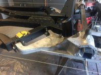
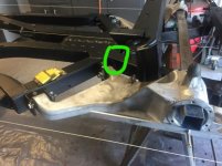
"Nichola" IMHO...the main source of rear chassis twist and flex originates from the area outlined.
I presume you have jigged your chassis to confirm that it is now "straight".
There are many differing opinions as to methods of rectifying the problem, and depends if you want to have the rear chassis looking concours in it's structure.
I am not a concours person or an engineer and this is my scenario based on what I did to strengthen the frame of my TR4 with IRS with the body on. Obviously I could have done a better job if I was working on a bare frame.
Weld a 65mm x 8mm x 900mm plates into the inside of the two main frame rails, centered on the outlined area. 65mm fits nice and snug between the top and bottom of the rails.
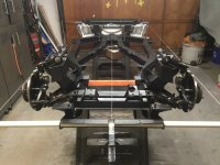
Boxed the rear suspension cross member upright supports to the chassis rails.
Remove [top] and bottom cruciform plates and weld in much larger/stronger plates from one outer chassis rail to the other side, with small cutouts to access the T/A mount bolts.
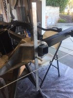
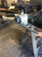
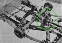
I have this additional arch [as seen on pic] on my TR,and welded braces from the top of it over to the rear suspension cross member, creating a box like figure to help strengthen the weak section that exists between the mid and rear chassis rails.
Like wise braces from the R/S cross member to the rear axle crossmember.
Some members will probably say that the above methods are OTT and put additional stress on other areas of the chassis. However there has to be ways of improving the original poor chassis design.
Anything is possible...but miracles take a bit longer...:D
 

Attachments

  • trchassis1_LI.jpg
    trchassis1_LI.jpg
    69.9 KB · Views: 114
Last edited:
Back
Top