. My BT7 does have a dedicated wire from the flasher (3 pins) to the indicator lamp on the dash.
They all do. the "P" pin of the flasher should go to the dash bulb. If it is one dash indicator bulb this wire should be either light green or light yellow. If there is one dash indicator bulb my point is that the other side of the bulb will be connected directly to a ground screw at the back of the tach. It will not go over to the turnsignal relay.
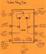
The flasher is connected between the fuse box and the flasher relay. I don't understand your statement here. Yes the flasher gets its power either directly from the fuse box or it gets it from the ignition switch depending on the year of the car. It gets its power coming in on terminal "B". Then the flasher sends "flashing" power out on terminal "L" to #1 terminal on the Turnsignal Relay, that should be a green/brown wire. When the flasher flashes effectively sending its flashing power to the #1 terminal on the turnsignal relay it also sends flashing power from the flashers "P" terminal to the dash indicator bulb. If this is a single bulb arrangement which some Healeys have this single bulb is grounded by a short wire to a ground screw on the back of the tach and then the bulb will flash as the turnsignals flash. If the Healey has two indicator bulbs on the dash then these bulbs respectively have there ground side connected to either the number 2 or the number 6 terminal of the turnsignal relay this is only in order to get them connected to the wire that is going to one of the front turnsignal bulbs which ever side is intended to flash.
If a ground is made through the relay, the flasher will switch the voltage to the relay and power the indicator lamp on the dash.
Maybe I can interpret your statement to mean this: When the turnsignal relay is energized to turn on the one side of the turn signals or the other, the turnsignal then connects the terminals #2, #6, #3, & #7 to their respective turnsignal bulbs and this causes the flashing power coming into the Relay on terminal #1 to be sent to its respective bulb. When the flasher is causing the outside bulbs to flash it is also causing the dash indicator to flash because the dash indicator bulb is connected to the "P" terminal of the flasher. Possibly I can interpret your statement about a ground is made through the relay as meaning that when the relay connect one of those previously stated terminals to the outside bulbs that allows the dash indicator bulbs to get grounded by a path that is going out to the filaments of the outside bulbs. BUT THIS ONLY APPLYS IF THERE ARE TWO INDICATOR BULBS ON THE DASH. IF THERE IS ONLY ONE INDICATOR BULB ON THE DASH THIS SCHEME DOES NOT APPLY. If only one indicator bulb on the dash it has a ground wire connected to the back the tach and the turnsignal relay is not relevent.
The direction switch (trafficator) provides the connection to the ground through the correct signal lights.
The trafficator energizes the turnsignal relay by energizing either terminal #4 or #8 which ever side is chosen. This then closes in the relay making terminal #1 which is the "flashing power" from the flasher gets itself connected to the respective outside bulbs. So when you say the trafficator provides a connection to ground, that's not terminology that I understand. The trafficator energized the turnsignal relay which in turn energizes the turnsignal bulbs. And yes that ultimately does provide a ground path for the dash indicator bulb. BUT AGAIN I HAVE TO SAY, "ONLY IF THERE ARE TWO INDICATOR BULBS IN THE DASH" If there is one bulb this bulb is not connected to the turnsignal relay.
Somewhere there is a phantom ground that is activating the flasher but not powering the lights. The flasher relay is mostly hidden below the fresh air duct which makes taking measurements more challenging but I will give it another shot.
 Hi Guest!

 Hey - did you know if you click on the title of a thread it will take you to the first unread post since you last visited that thread?
 but were afraid to ask:
  STOP!! Never post your email address in open forums. Bots can "harvest" your email! If you must share your email use a Private Message or use the
  smilie in place of the real @
 Pretty Please - add it to our Events forum(s) and add to the calendar! >>