• Hi Guest!
    You can help ensure that British Car Forum (BCF) continues to provide a great place to engage in the British car hobby! If you find BCF a beneficial community, please consider supporting our efforts with a subscription.

    There are some perks with a member upgrade!
    **Upgrade Now**
    (PS: Subscribers don't see this gawd-aweful banner
Tips
Tips

Wedge TR8 starter solenoid details?

stever_sl

Member
Country flag
Offline
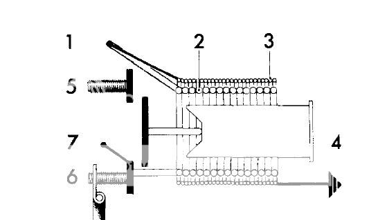
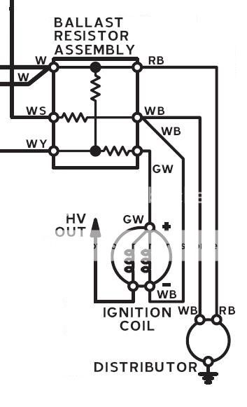
I have a TR8 that's so massively unreliable I don't dare drive it. Virtually every time I do, it dies somewhere, won't restart, and ends up being towed home. I'm trying to trace the path of current flow during starting and normal running, and I'm having some trouble visualizing what's going on at the starter solenoid. 4 terminals, 1 straight to the battery, 1 to the starter, but what about the other 2? I'd like to see an internal schematic showing how the coils work, and I used to have it years ago, but that computer died and the file is unretrievable. I have an ASCII picture but I was hoping someone had something a bit clearer? This is all part of a big effort to uncover what's actually going on in my car, which had an under-hood fire years before I bought it that resulted in a lot of plain white wires being spliced into circuits, not to mention installation of an upgraded distributor and many wiring detail changes around the ballast resistor and coil. I'm having no end of fun trying to reconcile the wiring diagram that I see most often, and the one in the Service Manual - but it all starts with that solenoid, so any help would be great!

- Steve Richardson
St Louis MO
 
Always helps if you tell us what year, as they aren't always the same. Here's what I see, based on 3 different schematics:

Of the two side terminals on the starter solenoid, one should be power to energize the solenoid, which is hot only when the ignition switch is turned to 'Start'. The drawings show it as either white/orange or white/red; powered by the starter relay, which in turn gets power from the switch.

The other is an output, a white/yellow wire that runs off to the ballast resistor assembly. It's used to compensate for the battery voltage dropping during cranking, by effectively shorting out part of the ballast resistance in series with the ignition coil.

Internally, the solenoid has two windings, both of which get power from the first connection I mentioned above. One winding is grounded to the case, so it has power applied as long as you hold the key into the 'Start' position. The other winding is grounded through the starter motor, which means it gets power applied only until the main contacts close. It's function is to provide some extra 'oomph' to help move the solenoid plunger, lever, starter drive and so on into the cranking position. But it draws a lot of current and would quickly overheat, so it only gets energized for a fraction of a second while the mechanism moves into place. Once it has moved, the smaller "holding" coil is enough to hold it there.

This diagram is from the TR6 ROM, but I believe the TR8 solenoid is similar.
untitled_5.jpg~original


PS, the above diagram makes it appear that terminals 6 and 7 are connected internally. But I believe the contact is, in fact, split so that they are only connected when the moving contact (the big vertical bar attached to the solenoid plunger) is touching them. Otherwise, the starter motor would short out the ignition when the solenoid is released.
 
Sorry, it's an 80 carbed convertible with A/C, U.S. specs. So the terminal with the white/red wire does the job of bringing the power from the start relay down to the solenoid, and pulls the solenoid over to connect the battery power directly to the starter (5 and 6 in the diagram) and also puts power to the white/yellow wire that feeds the ballast resistor - that's number 7 in this picture? Then that power gets shuffled to various places by the ballast resistor and ends up at the coil and distributor etc. Now I just have to go color-code some things on the total car wiring diagram. There seem to be two, the one that's in the Service Manual and another one that most people seem to use although it has a caution saying it's preliminary info only, but frankly the latter one is easier to follow. Thanks for the help!
 
Sorry, it's an 80 carbed convertible with A/C, U.S. specs. So the terminal with the white/red wire does the job of bringing the power from the start relay down to the solenoid, and pulls the solenoid over to connect the battery power directly to the starter (5 and 6 in the diagram) and also puts power to the white/yellow wire that feeds the ballast resistor - that's number 7 in this picture? Then that power gets shuffled to various places by the ballast resistor and ends up at the coil and distributor etc.
Right. Don't forget though, the white wire to the ballast is also hot. And there is no internal connection between WY and WS, the wires only cross. So power from WY doesn't get shuffled at all, it just goes to the coil (via GW) in place of the power that normally comes from the White wire (though an extra resistance).

In my experience on other cars, you don't actually need the power from WY at all. You can disconnect (and tape it up to avoid shorts) and the engine will still start and run fine. The WY connection is mostly useful in very cold weather, when the battery voltage drops a long way while cranking (or if the battery is nearly dead).

TR8%20BALLAST.jpg~original
 
Back
Top