Hi Guest!

 Hey - did you know if you click on the title of a thread it will take you to the first unread post since you last visited that thread?
 but were afraid to ask:
  STOP!! Never post your email address in open forums. Bots can "harvest" your email! If you must share your email use a Private Message or use the
  smilie in place of the real @
 Pretty Please - add it to our Events forum(s) and add to the calendar! >>
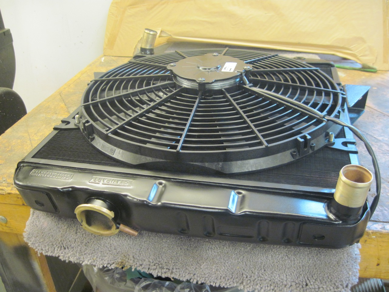
I know this subject can be found on various forums and threads but I thought I'd post my installation since it adds a little freshness to the topic. I noticed when I would slow cruise my TR the temperature would go up. Here in Reno, NV we have Hot August Nights with some open cruising at various venues. When in very slow, crawling traffic the engine would heat up and experience some vapor lock. I decided this year to convert to an electric fan and a Patton Machine fan eliminator kit. For $40 shipped the fan eliminator kit is a deal. There's someone else making these too but I went with the Patton. I read a lot of threads and decided to go with a PermaCool 16" electric fan. We have a Summit Racing warehouse near me so this fan was suggested and was available at Summit. I could have gone with a different fan but price was a consideration and it was reasonably priced. It covers the entire vertical height and horizontal width pretty good. I attached it to the radiator shell. I notched out the radiator shell so the square part under the head of the 1/4" carriage bolts I used would engage the notch and not spin when I tightened the nuts. The span of the fan prevents the bolts from moving out of the notched slots. The wiring was done partially with the schematic from https://www.hottr6.com/triumph/tr6fan.html . I used the brown-white wire that was connected to the headlight switch on a straight bullet connector. Per the above web-site, using the brown-white wire allows the ammeter to measure the current of the fan. If you don't use this wire the fan current will bypass the ammeter. I changed out the straight bullet connector above the steering column to a factory style H bullet connector I bought from one of the British car parts vendors and tapped off of it to a blade type fuse holder. The other side of the fuse holder went to the relay terminal 30 and terminal 87 went to the fan. I kept my fuse and relay under the dash to avoid cluttering the engine compartment. Both the relay and fuse holder had holes to mount them with screws. I replaced a couple of the bolts that held the brake pedal assembly to the chassis. I used longer bolts. Both the fuse holder and relay slide onto the threaded bolt but I don't need to put nuts on them because of the friction. I used 10 or 12 gauge wire to the fan and then a ground wire from the fan to the engine. I bought a hose adapter with a 3/8x18 NPT bung from a company I found online called Hollister Road Company https://www.hollisterroad.com/browse/?category=5106&page=1 . For $29.95 I received a 1-1/4" flanged hose adapter with a 3/8x18 NPT bung. Actually you could order a different size bung if you know what fan switch you're going to use.. They also have a lot of other stuff they manufacture too. I installed this hose adapter into the top radiator hose that I cut a small section out of. There is much discussion on whether to install the fan switch in the top or bottom radiator tank or in the top or bottom hose. I put it in the top hose, so there...so much for that. It works. This adapter also comes with a ground stud if you're using a single wire thermal switch. If you're using a dual terminal switch you don't need the ground stud. I originally had a dual terminal switch and used the above schematic. I liked that I could just tap into the fuse block with a spade connector on both the green and purple wired fuse positions. These leads will feed the DPDT switch which is wired to the switching side of the relay. The first thermal switch I used was a little high so I bought a lower temp switch but it had a single wire. I had to re-wire the DPDT switch and relay on the low side. I'll post a schematic of my wiring soon. Regardless of what position the switch is in; whether automatic or manual, the fan will only work with the ignition on which is different than using the schematic previously mentioned. In that schematic the fan can run with the key off. I didn't use the purple wire to my switch. I wired and taped the fan harness independent of the vehicles harness so it would still look stock but was an accessory to the car. The fan goes on at 195 and off at 180. I changed the thermostat to a 160 degree. The car runs much cooler when driving at speed. Doesn't matter much when idling and cruising. The fan comes on about 2/3 way up the gauge and turns off just above the mid point. I may play around with a cooler fan switch but it seems to be fine. I also added some Water Wetter to the coolant, just because. I'll post some pics and a schematic as soon as I can.
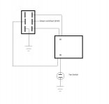
I attached a very crude drawing showing how I modified the original schematic I attached above to suit my single terminal fan switch. This lets me bypass the automatic function of the switch and when the switch is toggled the other way powers the switching side of the relay and grounds the relay to turn the fan on. The DPDT switch I'm using is a higher amperage switch than the switch that is detailed in the attachment that has the original schematic. I suppose the other half of the DPDT switch could be wired to the wires going to terminals 30 and 87 and just bypass the relay. The switch needs to be rated for the current draw of the fan plus any additional current added by the size of the wire and distance to the fan from the relay. The fan doesn't draw a lot of current per the factory specs.
I added some pics. Pic 3 shows how I mounted the fan with the carriage bolts. Hard to see the square notch in the radiator shell. I put a some vacuum caps on the threaded ends of the carriage bolts. Pic 4 shows the relay and fuse holder on the bolts I replaced. I put vacuum caps on the threads to help hold the relay and fuse to the 1/4-28 bolts. Pic 5 shows the 4-way connector I installed that replaced the 2-way straight connector. The orange-black wire goes to the fuse. The wire coming out the right side is a brown-blue wire that goes to the headlight switch. Pic 6 shows the DPDT switch mounted on the heater duct bracket. Pic 7 shows the new harness coming through the firewall. The fuse holder can be seen also.
Thanks for looking,
Art aka Renoman
Attachments
Last edited: