The VTR site articles are good, but I believe they only describe the wiring for a Delco alternator. Delco never used the 3/8" tabs that Paul described, so I don't believe that is what he has (especially since he is in Germany).
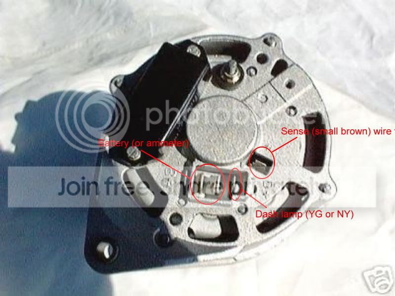
I hate to make assumptions when it comes to alternators, but if the arrangement looks similar to the 3 tab opening in the photo above, then I am going to guess that the two 3/8" terminals are the output. You will need to make up a new, heavy gauge (10 AWG will do, I used 8) wire that attaches to both terminals. Trying to run the full current through just one terminal will work at first, but is apt to lead to problems down the road.
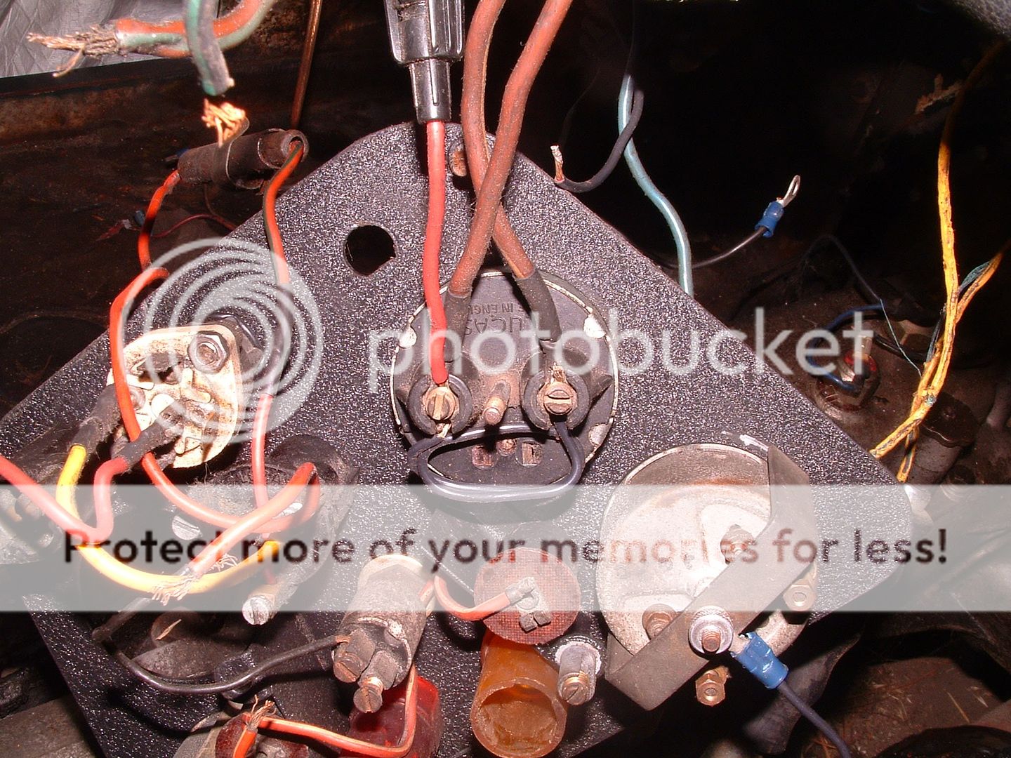
There are several ways to link the new output wire into the rest of the car. The simplest (and most often recommended) is to simply attach it to the hot post on the starter solenoid, where the heavy gauge cable to the battery is attached. That will work fine, but the ammeter will no longer work correctly and always show discharge even when the battery is being charged.
What I did instead was to join together the new wire along with the NU and NW wires where they originally attached to the control box (aka voltage regulator). That will correctly route the charging current through the ammeter. I then added a shunt across the back of the ammeter, to change the range from the original 30-0-30 to roughly 60-0-60.
The 1/4" tab is likely the output to the warning lamp (which depending on your alternator, may double as the excitation current when the engine first starts). You can use either of the original wires if you want to (the current is small); it needs to be connected to the small yellow wire that was originally on the 'D' terminal of the control box. That small yellow wire runs through the harness back to the red 'Ignition' warning lamp on the dash.
The alternator I used (an old Motorcraft) needed more excitation current than the dash bulb would pass, so I added a resistor across the back of the bulb. The symptom was that I would have to rev the engine up fairly high (like 3000 rpm) to get the warning lamp to go out and the alternator to start charging. If memory serves, I used a 10 ohm 10 watt resistor, and spaced it out somewhat away from the bulb base (so it couldn't heat the plastic too much).
In the photo above, at least, the stud is a ground point. Strictly speaking, as long as the mount is all metal, you probably don't need to ground the alternator separately. But I ran a heavy gauge (10 AWG) wire to one of the solenoid mounting bolts anyway.
Oh yes, don't forget that you must convert to negative ground (if it hasn't been done already). Hooking the alternator up backwards will very likely damage it instantly and there are practically no positive ground alternators available today. In addition to swapping the battery cables, you should swap the connections to the ammeter and ignition coil.

 Hey Guest!

 Hey - did you know if you click on the title of a thread it will take you to the first unread post since you last visited that thread?
 but were afraid to ask:
  STOP!! Never post your email address in open forums. Bots can "harvest" your email! If you must share your email use a Private Message or use the
  smilie in place of the real @
 Pretty Please - add it to our Events forum(s) and add to the calendar! >>