Hi Guest!

 Hey - did you know if you click on the title of a thread it will take you to the first unread post since you last visited that thread?
 but were afraid to ask:
  STOP!! Never post your email address in open forums. Bots can "harvest" your email! If you must share your email use a Private Message or use the
  smilie in place of the real @
 Pretty Please - add it to our Events forum(s) and add to the calendar! >>
CJD
Yoda
Offline
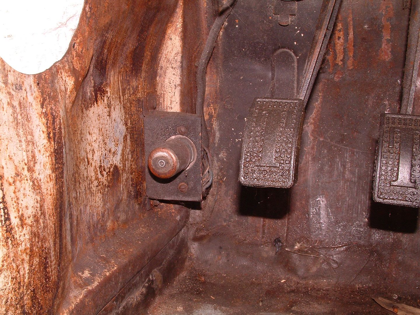
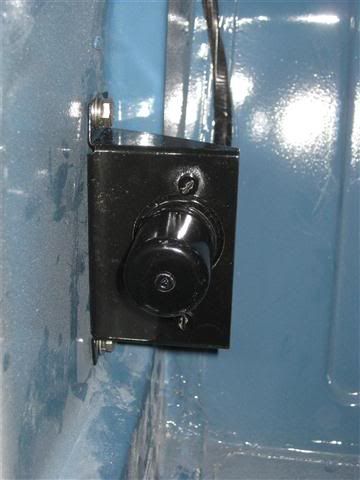
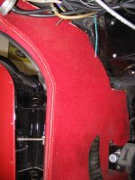
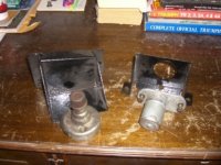
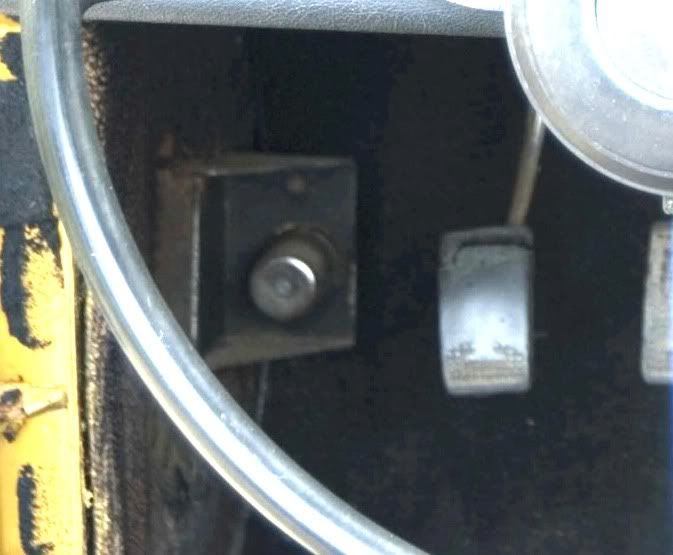
Here is a picture of the dipper switch on my car. You'll see that the mount bracket looks backwards. I tried reversing the bracket, but with the location of the original holes on the kick panel, this is how it had to be mounted at the factory. When reversed, the bracket will not sit in the kick panel recess unless I drill new mount holes.
So, is this common or is this an anomally?
John
So, is this common or is this an anomally?
John