• Hi Guest!
    You can help ensure that British Car Forum (BCF) continues to provide a great place to engage in the British car hobby! If you find BCF a beneficial community, please consider supporting our efforts with a subscription.

    There are some perks with a member upgrade!
    **Upgrade Now**
    (PS: Subscribers don't see this gawd-aweful banner
Tips
Tips

Thread size for 1275 coolant passage

CraigCootsona

Member
Offline
Hello all,

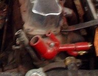
I have a 59 sprite with a 1275 (pre emissions model) and I would like to re-arrange the temperature sensor routing a little. I currently run with an electric fan whose thermostat is piped inline between the heater box and the on-off valve on the head. . . I know, not the best spot because of the risk of shutting that valve but I never close this valve. In the interest of a little more accurate sensing I would like to pipe the sensor directly into the threaded hole in head but can't find the correct thread size for the plug that is currently there. The plug is located at the front side of the cylinder head. Anyone know offhand what size?

Thanks,
Craig
 
Craig, I'm a bit confused about the plug you're refering to. Sounds like the plug where the temperature sensor for the Smiths dual gauge is mounted on my Midget, if so it's BSP (British Standard Pipe) thread, a non tapered pipe thread designed to seal with a flange and crush washer. You should be able to get an adaptor at a well stocked hydraulic hose shop. If you can find a T fitting then you can run both the sensor and the original sending unit bulb for the gauge similar to what I did with the modified thermostat housing on my 6 cylinder MGA project.
 

Attachments

  • 15124.jpg
    15124.jpg
    21.9 KB · Views: 234
OK, Bill I understand why you did that, but is there a chance that temp reading will be lower in the "dead flow" water space?
 
Naa, hot is hot and it is not that critical in any case.
 
Actually it will read differently (sometimes significantly!).
Craig
Since you have a Bugeye you probably have a radiator with the temp port there too.
Just run the fan switch from the radiator and the temp bulb from the engine block,that will give you the best of both worlds.

Bill
 
Craig,
I believe the thread size is 5/8-18. To double check this for yourself, pick up a 5/8-nf bolt and try it. As Bill said they are a straight thread meant to seal with a crush ring.
Bill, 3/8 BSP & BSPP (parallel pipe) are 19 threads per inch. This is why I believe it to be 5/8-NF. No written proof just what it measures in diameter and checks out to be in threads per inch.
Dug
 
Trevor, that isn't a dead space on that engine as there is a bypass port cast into the housing in that area which allows some coolant flow even it the thermostat is closed. Note the port above for the heater hose off the same bypass area. In this case it's a cast iron housing so I could braze an iron pipe adaptor in place and use common pipe fittings to mount the sensor and temp sender for the gauge.
 
Great. Thanks for the input everyone. Yes, when I removed this engine from the 1275 Midget, the smith's sensor was attached to the radiator and the head had a plug and crush washer. I think I'll follow Bill's suggestion and use the gauge input plumbed into the head and the fan sensor at the radiator. That would reduce and concerns with flow interruption.

Thanks again everyone!
Craig
 
Well, after over 9 years of thinking about it, I finally tackled this problem. The thread is confirmed as 5/8-18 UNF. The challenge was finding a thermostatic fan switch and adaptor that will get the switch close enough to the water. I finally used 1/8” NPT switch threaded into a sleeve that adapts to 5/8 18 straight thread because I could not find a fan switch with 5/8 thread.

I tried this setup with the fan switch in the head as planned but found it was too slow to respond, and caused wider swings in temp compared to the coolant going into the top of the radiator. It waited too long to come on at that location. Some of this could be caused by the fact that the switch is not directly in the flow, but rather, stands off a bit inside the adaptor.

As a result, I finally swapped the dash gauge sensor and the fan switch so the fan switch senses temp right at the radiator. The dash gauge sensor in the head is standard on later crossflow radiator 1275s and requires an adaptor 361-065 and crush washer 324-805 to prevent the sensor tube from bottoming out inside the head, and the adaptor has an internal surface that seals with the sensor tube (because straight threads don’t seal). Photo attached

I ran the engine through another temperature cycle and was pleased with the result. The thermostatic switch at the radiator came on at the expected temperature, probably aided by the turbulence of the coolant in that area allowing good flow to the sensor. Also, the temp gauge sensor in the block showed fairly accurate readings, also probably helped by its long tube that puts it well into the head.
 

Attachments

  • 8FB35FD7-42D5-4A4D-932B-92D58F65A9CF.jpg
    8FB35FD7-42D5-4A4D-932B-92D58F65A9CF.jpg
    59.3 KB · Views: 181
Last edited:
Thanks for the kind words. It's amazing how time goes by! It's hard to believe I've had this car for over 16 years and it still looks almost as good as when I restored it. The previous location of the fan switch was between the heater and the cylinder head water valve, because it was easy to use a brass tee fitting with two barb ends in the hoses and avoid the whole adapter mess. The only issue is I couldn't shut the tap to the heater because the water needed to flow over the switch. It wasn't best practice so now it's fixed. Now to install the brand new Sebring seats that have been sitting in my garage for the last several years. It's nice to have time to catch up on these things!
 
Back
Top