• Hey Guest!
    British Car Forum has been supporting enthusiasts for over 25 years by providing a great place to share our love for British cars. You can support our efforts by upgrading your membership for less than the dues of most car clubs. There are some perks with a member upgrade!

    **Upgrade Now**
    (PS: Upgraded members don't see this banner, nor will you see the Google ads that appear on the site.)
Tips
Tips

TR4/4A Temp gauge/sender question

Mink

Jedi Trainee
Country flag
Offline
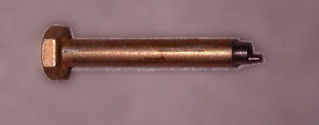
I have a quick question regarding the Jaeger temp gauge in my recently acquired '62 TR4. The car has sat for at least 15 years and I recently got it started again. Within minutes of starting, the temp gauge shoots to 250 degrees and stays there. I didn't believe the readings, so I set up an experiment - I put the sender in a pot of hot water on the stove and wired up the gauge to a 12V power supply. I used two different meat thermometers in the water as a control and found that my suspicions were correct - it's way off. I guess the cheapest route would be to swap the sender and see if that fixes it but I'm curious about the reliability of these temp gauges. Anyone have any feedback on whether I should start searching for a new gauge, too?

Here are some pics. With the water temp at about 170, the gauge is a needle-width below 250!

IMG_0352.jpgIMG_0354.jpg
 
Mink,

You should have a voltage regulator which regulates the voltage to the temperature and fuel gauge to 10V and not 12V so your gauge will not read accurately if you fed it 12V in your test.

Scott
 
You can test the sender with an ohmmeter. I have the following in my notes though I did not note the source:

Ohms -- °F

502 -- 100
320 -- 120
206 -- 140
139 -- 160
99 -- 180
72 -- 200
62 -- 208
 
Great info, thanks. I did not have a stabilizer in the circuit during my experiment. I guess that means that the stabilizer in my car is bad or the gauge was miswired. I'll also check the resistance of the sender against those numbers tonight.
 
A short time ago I searched the BCF forum and found that same resistance vs temp list. I did not remove my sending unit and felt no need to repeat that experiment, but think those values are a little high compared to my sending unit. I also found my voltage stabilizer to not be doing a very good job. After installing a better 10v regulator, I still had the gauge reading high. I had removed the t-stat, and verified in heated water with 2 thermometers that it opened at 185.

I decided to calibrate the gauge to the sending unit. My sending unit at 185 degrees is about 51 ohms. My temp gauge shows 185 with 85mA of current. So, with a 10v source (and a 51 ohm resistor as a sending unit), I moved the little slots in the back of the gauge to indicate 185. I'm not sure the difference between the right slot and left, so I doubt any temperature outside 185 is anywhere near accurate -but I'm happier with the gauge reading centered. If you decide to go that route, be sure to not short the slots to the case during adjustment. To be sure, I removed it from the case during adjustment.
 
I'm not sure the difference between the right slot and left,
I forget which is which offhand, but one of them affects the entire range equally, while the other affects mostly the 'hot' end. In other words, "zero" and "full scale".

A simple tool makes it a lot easier to move the slots (which move side to side rather than turning as you might think). I made mine as a lathe project just for practice, but you could file down the tip of a cheap screwdriver instead.

GAUGEADJUSTMENTTOOL.jpg~original
 
Thanks for the excellent info, gents. Very helpful. I went out to the car and found that the "I" terminal on the voltage stabilizer had nothing connected to it. So obviously the temp gauge was getting full battery voltage, certainly part of the problem. Then I tested the output of the stabilizer and it was all over the place between 0 and 3 volts. Not good. As expected, when I retried the experiment with this stabilizer in the circuit, the gauge read very very low.

So I tested the sender with the numbers Geo Hahn gave above and I tracked with them pretty closely:

208 61Ω
200 70Ω
180 98Ω
160 140Ω
140 206Ω
120 312Ω
100 477Ω

So it looks like the sender is ok and a new voltage stabilizer is my next purchase. Thanks again for all the help so far!
 
That does sound like a faulty voltage stabilizer but as I recall it is hard to test one with a digital voltmeter as it works by flipping the onboard voltage on & off rapidly to approximate 10VDC. Okay, that explanation probably reveals my limited grasp of such things.

In case you don't know, there are solid state versions available as well as the original thermal bimetal unit.

More info here:

https://bob_skelly.home.comcast.net/~bob_skelly/voltageStabilizer/voltageStabilizer.html
 
That does sound like a faulty voltage stabilizer but as I recall it is hard to test one with a digital voltmeter as it works by flipping the onboard voltage on & off rapidly to approximate 10VDC. Okay, that explanation probably reveals my limited grasp of such things.
On the contrary, I think you nailed it; except that it doesn't flip all that rapidly (even an old fashioned analog meter will still jump from 0 to battery voltage and back again).

One testing method is described at
https://drive.google.com/file/d/0B2H2NJt34OffWnpvYXJSZjR2VEU/edit?usp=sharing

Note that the electronic versions are polarity-sensitive. You can buy (or build) them either way, but they'll stop working if you switch battery polarity. (TR4s were originally positive ground, but many people convert to negative.)
 
Mink,
Once you get the stabilizer sorted out, take a look at an item that I got from Peter Sherman, an
Australian MG guru. (Attached)
FRank
 

Attachments

  • TR4 Temp adj.jpg
    TR4 Temp adj.jpg
    131.2 KB · Views: 161
Regarding the procedure for adjusting the gauge, how does one determine which is the hot side and which is the cold side? My gauge has no discernible markings on either adjuster or terminal.
 
Since you're going to adjust it anyway, easy way is to move each one with the gauge cold. The one that moves the needle is the 'cold' adjustment (which actually affects the entire scale equally).
 
Regarding the procedure for adjusting the gauge, how does one determine which is the hot side and which is the cold side? My gauge has no discernible markings on either adjuster or terminal.

I would consider the hot and cold adjustment "slots" to be as shown in Frank's picture link. That document shows the back side of the gauge in its normal orientation.
 
Back
Top