• Hi Guest!
    You can help ensure that British Car Forum (BCF) continues to provide a great place to engage in the British car hobby! If you find BCF a beneficial community, please consider supporting our efforts with a subscription.

    There are some perks with a member upgrade!
    **Upgrade Now**
    (PS: Subscribers don't see this gawd-aweful banner
Tips
Tips

Spitfire Spitfire Steering Column - Picture Request

dklawson

Yoda
Offline
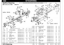
Our project Spitfire came to us as the previous owner's unfinished project.

The owner before them had lost the ignition keys so the last owner bought a new lock assembly and "cut" the old lock off. To do this they removed all the under-dash support brackets. What's there now is an ignition switch lying on what's left of the driver's footwell, and a pile of parts sitting below a steering wheel hovering in space.

I've looked in the VB catalog to see the general arrangement of the brackets and clamps. However, it would be very, very, helpful if someone were kind enough to direct me to a picture of (or post a picture of) the installed steering components on a Mk4 Spitfire. As it is, I'm not even really sure how far up or down the column the switch is supposed to be... and there must be a plastic cover for the lock that I am missing. It can't be exactly what it looks like right now!

Thanks in advance for any advice, dimensions, or pictures that you can share.
 
Well, after spending some time looking at the catalog diagrams, the diagrams in Bentley, and the pile of parts left by the previous owner, I may have figured out the general arrangement. I still need help with two things.

1) There is a welded assembly of two parallel tubes bent into a dog-leg shape. The ends are flattened to bolt against the steering column mounting clamp blocks. In addition to the dog-leg shape, one end is offset in height. Can someone explain to me if this part goes above or below the column and generally "which end is up"?

2) I do appear to be missing a plastic shroud that is supposed to surround the ignition lock. From Bentley it looks like this decorative shroud determines where the ignition lock should be on the column. If someone can describe or photograph the ignition key shroud this would be very helpful. Though I'll be asking a friend if he has an extra one... it looks like I am going to have to search for a lock shroud.

Thank you in advance.
 
dklawson said:
1) There is a welded assembly of two parallel tubes bent into a dog-leg shape. The ends are flattened to bolt against the steering column mounting clamp blocks. In addition to the dog-leg shape, one end is offset in height. Can someone explain to me if this part goes above or below the column and generally "which end is up"?
Doug - are you referring to item 13 in the attached?
 

Attachments

  • 12747.jpg
    12747.jpg
    96.3 KB · Views: 221
Hi Ross, yes I'm trying to understand how #13 fits up against the brackets. I know it looks like it's below the column with the "dog legs" pointed right and up, but it doesn't seem to fit very well that way. If that's really the way it's supposed to fit I'll just have to give it another go and see if perhaps I've got one of the other clamping parts on in the wrong position. I'm just looking for a bit of confirmation at this point.
 
My '78 does not have this arrangement otherwise I would go physically check it, but I believe you're on the right track.

The 'dog leg' part of that 'anti-torque tube' should face the bottom of the steering column and the bent legs should go up past the column and mount under the top half of the lower column bracket, and be sandwiched between the two lower bracket felts. The upper mounts should attach below the bottom half of the upper column clamp. If you're having trouble with the length of the anti-torque tube, the upper column clamp is moveable up or down the column. Otherwise it should fit. The socket screws on the top clamp should pass through the anti-torque tube, then into the lower half of the clamp, through the upper half and into the tapped plate on top.

Note that, although it is not shown on the VB parts diagram, in the British Leyland book there are two part numbers for that anti-torque tube. Part number 154977 is the 'standard' part number, but they also specify part number 156559 for Sweden-only. I'm not at all sure what the difference would be, but I just mention it in case you might have the wrong part.

Otherwise, there is only one way that tube should really fit in there and if it doesn't line up maybe the upper or lower brackets are not fit quite right. Again, the upper clamp should slide up or down the column a bit, and the lower clamp is adjustable vertically via the upper clamp bracket.
 
Thanks Ross. Weather permitting, I'll get this sorted out this weekend.
 
I got the steering column back in place today with much swearing, body contortions, and some carefully selected shims. What confused me from the exploded diagrams and the various bits left by the last owner was I didn't know the relationship of the column mounted ignition switch and the welded bracket. I now understand why people convert to a dash mounted switch. UGH!

It took forever to get the switch in place, the weldment attached... but not too tight... so all the fasteners could be started (and subsequently tightened) without binding. What I thought would be a simple hour job turned into an afternoon. The upshot of today's steering work has spawned my next question/post.
 
Back
Top