-
 Hi Guest!
If you appreciate British Car Forum and our 25 years of supporting British car enthusiasts with technical and anicdotal information, collected from our thousands of great members, please support us with a low-cost subscription. You can become a supporting member for less than the dues of most car clubs.
There are some perks with a member upgrade!**Upgrade Now**
(PS: Subscribers don't see this gawd-aweful banner

Tips
- We have a special forum called "Member Articles" where you can submit actual articles for consideration for publication. Learn More
- Don't have an Avatar? If not, your avatar will default to the 1st character in your username. Go into "Account Details" to change your Avatar.
- Some basic forum navigation info: click
 Hey - did you know if you click on the title of a thread it will take you to the first unread post since you last visited that thread?
- Hey Guest - Is your British Car Club in our Clubs database? If not, send me a PM - Basil

- Looking for a local club? Click the "Clubs" tab above and browse hundreds of clubs world-wide.
- Add Android or iPhone APP: click
- Did you know - any picture or video you add in your posts in any marque-specific forum will also get added to the Media Gallery automatically.
- A few more tips about posting and replying: click
- Hey there Guest - be sure to keep your profile page up to date with interesting info about yourself: learn more
- More tips and tricks on Posting and Replying: click
 but were afraid to ask:
  STOP!! Never post your email address in open forums. Bots can "harvest" your email! If you must share your email use a Private Message or use the
  smilie in place of the real @
- Want to mention another member in a post & get their attention? WATCH THIS

- So, you created a "Group" here at BCF and would like to invite other members to join? Watch this!
- Hey Guest - A post a day keeps Basil from visiting you in the small hours and putting a bat up your nightdress!
- Hey Guest - do you know of an upcoming British car event?
 Pretty Please - add it to our Events forum(s) and add to the calendar! >> Here's How <<
- Hey Guest - you be stylin' Change the look and feel of the forum to fit your taste. Check it out
- If you run across an inappropriate post, for example a post that breaks our rules or looks like it might be spam, you can report the post to the moderators: Learn More
- If you would like to try some different "looks" or styles for the site, scroll to the very bottom, on the left and click the Style Selector.
You are using an out of date browser. It may not display this or other websites correctly.
You should upgrade or use an alternative browser.
You should upgrade or use an alternative browser.
Roller Rocker arm Pics
- Thread starter Dadandson
- Start date
blkcorvair
Jedi Knight
Offline
Looks great. How do you mean you designed them? Whats the ratio?
blkcorvair
Jedi Knight
Offline
Oh so you mean you really designed them! I thought maybe you cross fit something else. Major 
Trevor Jessie
Yoda
Offline
Stock pedestals?
Why did you retain the springs instead of going with solid spacers?
Why did you retain the springs instead of going with solid spacers?
Hairyone
Jedi Trainee
Offline
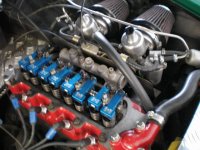
They do look well cool, just need a transparent rocker cover to show them off.
1st Q why? are ratio roller arms not available?
2 have you any pics before assembly
3 how have you held the roller in.
I am glad that there are people out there across the pond with great love for these cars, who are designing & improving bits.
Excellent work
Adrian
1st Q why? are ratio roller arms not available?
2 have you any pics before assembly
3 how have you held the roller in.
I am glad that there are people out there across the pond with great love for these cars, who are designing & improving bits.
Excellent work
Adrian
OP
Dadandson
Jedi Trainee
Offline
The material is 6061-T6 Aluminum. The rollers are hardened O-1 to 58-62 Rc. The stock pedestals seemed to work fine and David Vizard prefers springs to solid so there is absolutely no lateral movement. The roller is held in with a press fit cross pin. The bushing on the rocker shaft is a material called "Oilight Manganese Bronze". These are preferred over needle rollers because needles will fail eventually and that would cause catastrophic failure.
My whole goal was to design rocker arms that could be installed by a novice, that requires no machining or modifications of OEM parts (the rocker shaft would almost always need to be replaced) and improve performance. I am going to put a few miles on the car and tear the rocker train back apart and see how they look. If they are holding up, and I have the utmost confidence they will, I will make a few more sets and put them on eBay and see what happens. BTW, my target price is under $200 a set.
My whole goal was to design rocker arms that could be installed by a novice, that requires no machining or modifications of OEM parts (the rocker shaft would almost always need to be replaced) and improve performance. I am going to put a few miles on the car and tear the rocker train back apart and see how they look. If they are holding up, and I have the utmost confidence they will, I will make a few more sets and put them on eBay and see what happens. BTW, my target price is under $200 a set.
Whitephrog
Luke Skywalker
Offline
Tim
You will likely have a ready market waiting on you.
You will likely have a ready market waiting on you.
jhorton3
Jedi Warrior
Offline
Tim-I'm very impressed! They look great. What cam are you running in your engine and what's the rev limit with these over stock units? If you've got a dyno shop somewhere around you might want to put stock back on, test, then put your new ones on to see what running differences there are between the two.
OP
Dadandson
Jedi Trainee
Offline
I have a stock cam, at least I have not changed it. I am reluctant to put the car on a dyno as I have seen motors blow on them. It is still the same tired short block that was in the car when I bought it. I have to rebuild the rear axle, gear lube leaking, then I am going to build a short block. After that I will go to a dyno. I have been working on this rocker arm/head project for the last 4 months off and on, I still have a business to run, so it make take quite a few months before I can say exactly what the benefits of these arms are. I will keep everyone updated and again this project would not have gone as it has without the direct and indirect help from everyone on this forum. This will be a success for all of us. Thanks again.
Trevor Jessie
Yoda
Offline
In a nutshell, what did you change on the geometry to get more lift? This is an important question because (and someone correct me if I'm wrong) some high lift cams may cause the angle of the pushrod to be great enough to rub the head depending on the rocker geometry.
blkcorvair
Jedi Knight
Offline
Whitephrog said:Tim
You will likely have a ready market waiting on you.
Agreed.
Are you hiding them under a stock valve cover? or alloy neccasary for clearance?
OP
Dadandson
Jedi Trainee
Offline
By changing the dimensions of the fulcrum center, rocker shaft, to the roller and adjusting screw more or less lift can be created. The lift on a stock cam is .270" and the stock dimension of the fulcrum center to the valve center is fixed. So using a CAD, computer aided drafting, I was able to position the centerlines to obtain more "Lift". I was very careful to insure that the push rods would not rub on the head openings. This setup will fit under both stock or alloy covers. There is actually less room under an alloy cover as the side walls are tapered and the stock cover walls are straight. Again, my goal was to design rocker arms that increase performance and could be installed without removing the head or making any other changes to the OEM equipment. Even the adjusting screws on the arms are OEM. That's why I was asking in a previous post where I could get a 9/32-26 BSFT tap.
Correction: The alloy covers have more room vertically but the OEM covers have more room width wise.
Correction: The alloy covers have more room vertically but the OEM covers have more room width wise.
Trevor Jessie
Yoda
Offline
So... you only shortened the distance from fulcrum (rocker shaft center) to the adjustment screw center. Correct?
OP
Dadandson
Jedi Trainee
Offline
I adjusted both as the roller moves from one side of the valve stem to the other. By only moving the adjusting screw an interference issue with the head may arise. Vizard says you can elongate the holes in the rocker towers and achieve what you describe with OEM arms.
Trevor Jessie
Yoda
Offline
Trevor Jessie
Yoda
Offline
OK... I think there is an issue there that needs to be addressed. But I'll leave it for an engineer. (I'm a scientist).
