• Hi Guest!
    You can help ensure that British Car Forum (BCF) continues to provide a great place to engage in the British car hobby! If you find BCF a beneficial community, please consider supporting our efforts with a subscription.

    There are some perks with a member upgrade!
    **Upgrade Now**
    (PS: Subscribers don't see this gawd-aweful banner
Tips
Tips

rocker arm fitment - how close to 'center'?

64rocksprite

Jedi Trainee
Country flag
Offline
Well, I'm stuck until you all can help me out with this one.
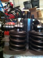
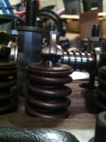
I installed 1.5 rockers from MiniSpares, which came with specific taller pedestals.
I've tried to get the rocker pads centered, but you can see I have a few that are a bit off center, but are up against the pedestal, so it's not a shim (or remove shim) question.
So..I would think ideally these need to be centered, but are these off enough that I need to take off some material..or ??

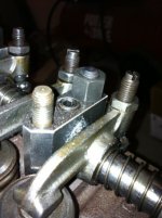
Final related question:
The new rocker shaft has a set screw that the old pedestal washer/tab won't fit over as it sits proud of the top of the pedestal. Do I need these tabs? or can I substitute a washer? Or should I grind this set screw down flush? I guess its not obvious to me why we need a tab on top of a solid block of steel?

Appreciate your input.
PS: I think I need to get Drew's set-up where he had an old laptop in the garage..cleaning up so I can come inside and type this is costing me valuable shop time! :hammer:
 

Attachments

  • 27027.jpg
    27027.jpg
    67.4 KB · Views: 305
  • 27028.jpg
    27028.jpg
    63 KB · Views: 299
  • 27029.jpg
    27029.jpg
    63.1 KB · Views: 303
  • 27030.jpg
    27030.jpg
    66.7 KB · Views: 306
With my 1.5 Titan roller rockers I had a left hand and right hand rocker. If you think that you may have this issue you will need to move them around to obtain your best fit, it took me many hours to find the best combination, but don’t sweet it if you can’t achieve the perfect center. You just want to cover the entire top of the valve stem. I had to make and install 0.125 shims to sit under the rocker stand to achieve the correct ratio angle; if you need shims to obtain the right ratio APT has them in stock.

Ideally what you’re looking for is a straight line looking at the side view through the center of the adjuster ball through the center of the rocker shaft to center of the of the nose end of the rocker. You would find your best results with a dial indicator to set everything up so that you know your heading in the right direction with your valve lift. You want to have the highest contact point of your rocker in the center of your valve stem. 1.5 rockers are suited best with the corresponding 1.5 camshaft for best results.

All of this is relevant to head and deck heights. If your block was milled or you head milled to increase compression ratio’s you will have to shim the rocker stand to compensate for cutting that metal away, in my case, I need .0125” shim to give me the .430” valve lift that the cam spec stated. You can also go about it a different way and have custom made push-rods from Smith Brothers to achieve your best rocker to valve stem geometry too, either way they, both will work.

As far as your rocker shaft tab I would put some loctite on it and secure it good. I would also use harden flat washers under the head nuts and rocker nuts. Be sure that your oiling hole corresponds correctly with the correct rocker stand and rocker shaft, or you could have a bad day starving the rockers for oil.
 
The pedestals should be the right height for his arms to maintain the correct geometry as they came with the 1.5 arms from Mini Spares. However, it certainly would be a good idea to confirm that no height shims are needed.

As above really on the left/right centering of the pads. Some arms may be better than others. The forged arms from the factory had the same issue so this is not unique to the new arms. On the 1275s with stamped metal arms (like the Austin America) the pads on the tips of the arms were oval to keep hardened pad material on the top of the arms in spite of the offset.
 
Doug said:
As above really on the left/right centering of the pads. Some arms may be better than others. The forged arms from the factory had the same issue so this is not unique to the new arms.

Yup. Do some "arm juggling", you may find a more acceptable arrangement.
 
Thanks all. I'll have a go at re-arranging and checking the height. The head was skimmed, so I'll double-check the pedestal height. Unfortunately, it was done by the previous owner, so I don't know how much was taken off.
Appreciate the info, that should get me back to work!
 
When higher ratio rocker arms are used it is common to increase the vertical location of the rocker shaft by somewhere between 0.060 and 0.100". Also, the shaft location is moved horizontally towards the pushrod side as well. With the change in rocker ratio, this is necessary to keep the pushrods and the rocker tips in line with the existing configuration of the head. This can be verified by using the old locating tab and see where the slot falls in relation to the socket screw. It should fall on the spring side of the screw.

Regrinding cams reduces the base circle. Combination of higher lift and narrowing the lobe centers reduces the base circle more. Cutting the block or head helps bring things back towards production geometry. Usually however, not enough on race engines to make up the difference. So, longer pushrods and longer adjuster screws are employeed.

Heavily re-cut valve seats on the valve itself and in the head make the location of the valve stem tip higher above the head to pedestal surface also potentially requiring some shims under the rocker pedestals to get some additional clearance under the rocker arm for the spring/retainer edge. Also, one is back to potentially having longer pushrods and longer adjusting screws.

All this messes with the original geometry. Compromises in all places unfortunately.

Look at the gasket surface of the head. There is usually a casting offset under the center exhaust port about 0.040"-0.080" below the face. If that is still there, then I would speculate that the head has not been cut more than 0.010". Usually, it takes about 0.004"-0.006" to clean up a head. Cylinder heads start "cupping" down the center from the heat. That is why the usually blow the head gasket between cylinders or out the front and rear in the center of the block. Takes about that much to clean up the head, minimum.

I'll measure a stock uncut head tonight (have one on the bench) and report back what the thickness measures. Give an idea (+/- 0.010") of what an unmolested stock head's thickness happens to be.

Take care,
Mike Miller
 
Measured 5 stock heads last night. Three 12G1316's and two 12G940's. 2.742" - 2.746" thick. Not much variance in production perspective. On 1275's about 0.012" is a cc of volume reduction in the combustion chamber. 1 cc changes compression about .2 of a ratio if you start from 8/1 and about .25 if you start from 8.8/1.

HTH,
Mike Miller
 
Thanks Mike, appreciate you taking the time to measure those.
I'll be pulling the rocker assy off this week and will flip the head over.
Where where you measuring to get the 2.74"?

Thanks again,
Devin
 
Measured from valve cover gasket rail above the center exhaust port to the underside. Used a Fowler 2-3" micrometer with rolling digits. Vernier caliper could have been used too.

You're welcome,
Mike
 
Back
Top