
-
 Hey Guest!
British Car Forum has been supporting enthusiasts for over 25 years by providing a great place to share our love for British cars. You can support our efforts by upgrading your membership for less than the dues of most car clubs. There are some perks with a member upgrade!**Upgrade Now**
(PS: Upgraded members don't see this banner, nor will you see the Google ads that appear on the site.)
You are using an out of date browser. It may not display this or other websites correctly.
You should upgrade or use an alternative browser.
You should upgrade or use an alternative browser.
MGB Reverse and overdrive switch
- Thread starter Boggsy64
- Start date

WillR
Jedi Warrior
Offline
I had the same thought when i was last under my car replacing the reverse switch. Drivers side of the tranny a bit higher up was another switch that looked about the same as my reverse. I cant remember what color wires ran in to it off the top of my head. In my 78 it some how advanced the timing in higher gears to help with all the smog stuff. John Twist mentions it has a tendency to let smoke out and recommends it be unplugged. I didnt notice any other switches then those two. Where was your switch located
OP
Boggsy64
Jedi Hopeful
Offline
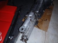
Bob here is a pic. The one on the top and to the left is the one i assume is the " OD" switch as seen in schematics and Moss parts diagrams. The one on the right I assumed is the reverse switch. There is also an additional aftermarket reed switch added to activate off the end of the rod that comes out of the shift top. None of the reverse circuits are working and I will have to sort this out. I assume the wires were just connected but not in any rational manner.
Attachments
Looking into this it looks like the trans tops were standard for o/d or regular 4 speeds. The switch that is attached to the shift tower is for overdrive. The trans top I pulled did not have anything going to that switch. The switch was also present just like yours. Looks like there is a spare switch sitting there for when you need it. I was thinking 3 syncro MGB transmissions when I said the shift towers did not interchange. There is still some interior bits missing on the shift tower to use one on a overdrive car if I am seeing this correct. Bob
homebeforedark
Senior Member
Offline
One of the two remaining switches controlled the 'Fasten Seat Belt' light on the later MGB. The light would come on in any forward gear if you didn't have your seat belt buckled.
homebeforedark
Senior Member
Offline
Now I remember what the third switch is for. It controls the fourth gear advance solenoid on top of the brake and clutch cylinder cover. I repaired many of those when I worked for British Leyland. (but that was thirty-four years ago)
OP
Boggsy64
Jedi Hopeful
Offline
I have a small solenoid operated valve of some kind mounted to the brake / clutch control box near the master cylinder. I thought this was an aftermarket windscreen washer pump of some kind. I will take a picture and post it. This may be the advance solenoid you are talking about. Mine is not connected to anything, but that is not unusual! There is another solenoid on the opposite side of the engine bay that was not electrically hooked up either. The vacuum lines from this go to the distributor and other areas. I will post a pic of this as well. I have pulled the wiring harness, that went to the transmission, up into the engine bay and there are definitely 4 wires for two switches. I will have to clean off the wires and go through the diagram to see what they are.Now I remember what the third switch is for. It controls the fourth gear advance solenoid on top of the brake and clutch cylinder cover. I repaired many of those when I worked for British Leyland. (but that was thirty-four years ago)
OP
Boggsy64
Jedi Hopeful
Offline
Now I remember what the third switch is for. It controls the fourth gear advance solenoid on top of the brake and clutch cylinder cover. I repaired many of those when I worked for British Leyland. (but that was thirty-four years ago)
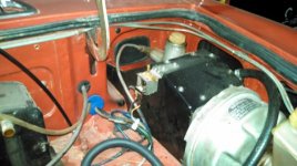
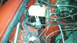
Here are pictures of the two solenoids. The one that is on the left side of the engine compartment I believe is some sort of vacuum advance control as the vacuum line goes to the distributor (even though electrically was not connected, the leads were so loose they just fall off). The other pic is of a solenoid on the pedal cover box. The wire from this switch definitely goes to the area of the transmission with the two switches (Red wire with yellow trace). Looking at the Bentley wiring diagram for 77 B with Cat conv this wire is between the "spark control switch" and "spark control solenoid". So one of the switches on the transmission is to the spark control switch. Where are the vacuum lines from the spark control solenoid supposed to go? Nothing was hooked to this solenoid but the wires.
homebeforedark
Senior Member
Offline
There is an easy test for the 4th gear advance system. Start the engine and place the gearbox in the fourth gear position. If the engine revolutions increase about 100 RPM ,then the system is working properly. If not ,then check the electrical first. With the engine not running select fourth gear (with the ignition switch on ) and listen for the click from the solenoid. If no click then check the power to the solenoid. The switch on the gearbox rarely fails. Solenoids are almost as reliable. I say that because when I find them disconnected or improperly plumbed , then most of the time the system works when reconnected properly. I emphasize 'connected properly' because the system will not function properly if the vacuum lines are reversed. One vacuum line comes from the intake manifold to the solenoid and then the other line hooks to the vacuum advance. If you connect it the easiest way then it is wrong. The solenoid is also a dump valve. If the lines are reversed , then the ignition will stay at full advance until the solenoid bleeds down. This system was designed to meet a Federal specification. The thinking was that as you are accelerating through the gears , then the engine is under a load. But when in to gear you are cruising. The system will help on gas mileage and if you have to accelerate hard in top gear , then the manifold vacuum will decrease and there should be little chance of detonation.
Alan T
Alan T
OP
Boggsy64
Jedi Hopeful
Offline
Thanks Alan. What I believe to be my "4th gear advance solenoid", the one mounted to the pedal box, did not have any hoses on it. I can see the other one, on the left side of the engine compartment, has the "dump" hoses coming out the bottom. This one was not electrically connected as the connector on the ends of the wires was extremely loose. I will try to find a "plumbing" diagram for how the hoses from these two solenoids are to be connected to the distributor.