Hi Guest!


 but were afraid to ask:
  STOP!! Never post your email address in open forums. Bots can "harvest" your email! If you must share your email use a Private Message or use the
  smilie in place of the real @
 Pretty Please - add it to our Events forum(s) and add to the calendar! >>
Greetings Fellow Members!
If you're a restoration purist, please stop reading here. I'm sure my question and surrounding detils will only bring tears to your eyes .
.
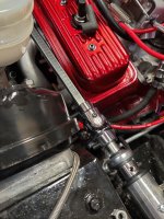
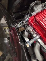
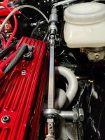
I recently bought a restomod TR6 that I'm in the process of cleaning up and improving where I can. I've run into a bit of an issue that I'm struggling to resolve and thought perhaps somebody out there has already tackled it or is just more clever than I about steering. My car has a Chevy 4.3L small block six. Nothing crazy for horsepower, but it does fill up the engine compartment and things are tight. This includes the steering shaft. The original modifier had taken the standard shaft, spunt it around, added a few welds to include a u joint snaked through the center header pipe curve. Clearance was almost non-existent - maybe you could slide a piece of paper bebtween it and the block. Anyway, everything was pretty rusted and the only way to get the header out (or likely change a spark plug) was to cut out the steering shaft. Didn't want to replace what I thought was a bad and unsafe design, but now I can't figure out how to do it better. Using all 3/4" DD shafting, I've added two additional U joints, 3 himes and one double Universal to try route it over top of the header pipes and take a nose dive down (using the double U) to the steering box. The angle is just too steep. Attached a couple of pics to help visualize. Just wondering if anybody out there has had to tackle this problem and can recommend alternatives. BTW, I have thought of going under the header, but that seems to have even more obstacles

Thanks!
Mike
If you're a restoration purist, please stop reading here. I'm sure my question and surrounding detils will only bring tears to your eyes
. I recently bought a restomod TR6 that I'm in the process of cleaning up and improving where I can. I've run into a bit of an issue that I'm struggling to resolve and thought perhaps somebody out there has already tackled it or is just more clever than I about steering. My car has a Chevy 4.3L small block six. Nothing crazy for horsepower, but it does fill up the engine compartment and things are tight. This includes the steering shaft. The original modifier had taken the standard shaft, spunt it around, added a few welds to include a u joint snaked through the center header pipe curve. Clearance was almost non-existent - maybe you could slide a piece of paper bebtween it and the block. Anyway, everything was pretty rusted and the only way to get the header out (or likely change a spark plug) was to cut out the steering shaft. Didn't want to replace what I thought was a bad and unsafe design, but now I can't figure out how to do it better. Using all 3/4" DD shafting, I've added two additional U joints, 3 himes and one double Universal to try route it over top of the header pipes and take a nose dive down (using the double U) to the steering box. The angle is just too steep. Attached a couple of pics to help visualize. Just wondering if anybody out there has had to tackle this problem and can recommend alternatives. BTW, I have thought of going under the header, but that seems to have even more obstacles
Thanks!
Mike