• Hi Guest!
    You can help ensure that British Car Forum (BCF) continues to provide a great place to engage in the British car hobby! If you find BCF a beneficial community, please consider supporting our efforts with a subscription.

    There are some perks with a member upgrade!
    **Upgrade Now**
    (PS: Subscribers don't see this gawd-aweful banner
Tips
Tips

Rear shroud connection to the floor pan on a BJ7

bob hughes

Luke Skywalker
Country flag
Offline
Hi Guys

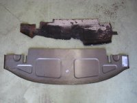
A bit of help required. I am in the process of fitting in a new floor to the boot (trunk) of my car as the existing one is somewhat wrecked - rust and filler in equal quantities.

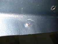
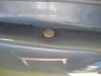
I have looked around it and there appears to be holes at around 100mm,- 4 inch centers around the bottom of the shroud where it mates with the rear of the floor pan, though in my case, fixings have been fitted in only a few places, and I am not sure what they are.

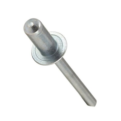
Questions - I guess that there should be a fixing in every hole? when I get around to that part, and the next question is what to use, will pop rivets do and should they be the countersunk ones? or what.

:cheers:

Bob
 
The holes are for regular rivets, but pop rivets work well and you can fill the centers if you like and no one will know the difference. Fitting original rivets requires a rivet squeezer or a rivet gun with suitable buck (and some practice if you haven't done riveting before). I put a strip of electrical tape on both flanges to prevent electrolytic corrosion between the steel pan and aluminium shroud. It's a good idea to seam-seal the gully formed at the top of the pan/shroud boundary as it can trap water and encourage rust. The outside of the flanges were painted flat or satin black at the factory to make the flange less noticeable (a detail sometimes missed by even the best restorers).

Edit: I bought a bunch of rivets from an aircraft supplier, but when I realized I'd need a rivet cutter--the available ones were too long--and a squeezer or gun and buck I gave up and used pop rivets on our BN2.

Edit 2: No countersinking necessary; originally, it appears the pan and shroud were mated up and holes drilled through the two. I don't think there was any jig or measurements used as the holes aren't exactly spaced.
 
Here is a tip I learned the hard way. At least temporarily, fasten the rear flange of the new floor to the bottom of the shroud using either a few rivets or bolts before you weld the center supporting brace to the new bottom. That way you will weld it in the correct location. I didn't do that on my BT7. I just installed the new bottom panel and then welded the brace where it landed on the new bottom panel. When I finally installed the rear shroud, the rear lip of the new floor panel did not line up with the rear shroud flange. I had to cut the brace loose and reposition and reweld it once I had the floor and shroud flanges bolted together. Hope that makes sense.
 
Thanks Bob and Rob, I will make sure I follow those comments up but I am working with the shroud in place so may not encounter your problem Rob unless things go horribly wrong.

First of all I have to cut the old stuff out, just plucking up courage to get the cut off tool out and make a start. All the new stuff has arrived, including a bright shiny aluminium petrol tank and sender along with tank straps and clevis pins to replace the home made stuff a PO had put in. The home made Ali tank must be worth something to someone over here, if they are suffering short arms and long pockets. It worked for me since 2002 when I first bought the old girl, it is a shame that who ever built it could have just spent a bit more time on the details, like a sunken sender area and may be the sunken drain area.

Thanks again

:cheers:

Bob
 
Bob, Here's a photo of what my boot panel looked like when I cut it out. Just grab the cut off tool and start in.
 

Attachments

  • IMG_4722.jpg
    IMG_4722.jpg
    50.6 KB · Views: 184
Yup, will do, just got the garden to sort out a bit then I will be into it. I doubt that I will have much more to show than you did, i will post a picture of the debris shortly.

:cheers:

Bob
 
While solid rivets were originally used, I'm sure there's a high percentage of Healeys today wearing easy to install pop-rivets.

My recommendation would be to use the "closed end" variety, to exclude moisture. A smear of spot-putty will fill the hole where the mandrel popped off, and they will resemble a solid rivet.

Available from numerous sources, so shop around: https://www.aircraftspruce.com/cata...MI1uHRuYDP6AIVhJ6fCh0mKQ-IEAQYBCABEgIamvD_BwE

There are a wide variety of aircraft pop rivets available (usually a goldish Cad-plated color) but one of our airframe mechanics can educate you on them (I used on my rear shroud & for the oil cooler duct/screen).

04-02334b.jpg
 
I used the flat head rivets on my car and if I had to do it again, I would use the pop rivets and fill the holes with filler. I had to cut each flat head rivet to length, make a tool to set the head and go through some careful work to get them crimped. The pop rivets would have been much easier. Here is a photo of the tool I made and the end result, front and back.
 

Attachments

  • IMG_0640.jpg
    IMG_0640.jpg
    28.7 KB · Views: 166
  • IMG_0225.jpg
    IMG_0225.jpg
    38.7 KB · Views: 173
  • IMG_0224.jpg
    IMG_0224.jpg
    68.3 KB · Views: 180
  • IMG_0228.jpg
    IMG_0228.jpg
    44.3 KB · Views: 171
Thanks every body, all useful information, I will try and escape the clutches of the catering management, tomorrow, who is pursuing me to keep working on the garden, after all a chap needs a bit of R&R, don't you agree. :highly_amused:

:cheers:

Bob
 
Ah I think it may be because I have used google photos, I will try and sort it, though yesterdays ferrous mining revealed even worse dramas.

Mmmm it only works for me when I log onto Google ?

Any Ideas?


:cheers:

Bob
 
Last edited:
OK I have created an Album called Austin Healey, this should be the link


https://photos.app.goo.gl/3wq9g1ZJUc47h4s77


It seams like you have the lot, I will have to create specific albums dealing with each section for the future.

A case of new technology meeting and old head !!

The last image containing my big feet shows the right hand side of the floor in all it's glory mostly fiber glass and paste. The chassis extension leg has a generous helping of the same materials and the rear shroud support rail leg is in a similar state. The rear cross chassis member is nicely rusted at each end where it meets the box boot sections. This is not going to be a five minute job.

:cheers:

Bob
 
Last edited:
It looks like you have to share the photos in your google album. I don't use any cloud service anymore because it could end at any time, sometimes without warning.
 
Back
Top