Hey Guest!

 Hey - did you know if you click on the title of a thread it will take you to the first unread post since you last visited that thread?
 but were afraid to ask:
  STOP!! Never post your email address in open forums. Bots can "harvest" your email! If you must share your email use a Private Message or use the
  smilie in place of the real @
 Pretty Please - add it to our Events forum(s) and add to the calendar! >>
roscoe
Jedi Knight
Offline
I am making the post I wish I'd found when I searched before I began the job of changing out my 4.11 rear end gears for a 3.54:1 crown wheel and pinion. Many on this forum have had this done and I'm sure if there is someone who has actually done the work themselves they will speak up. For those that may not know, the 3.54 gear set was used in those big Healeys that came without the Laycock de Normanville overdrive.
Oddly to me, many have overhauled engines and a smaller number have done gearboxes but most folks stop at changing these parts out and take these to a ring and pinion shop or at least someone who has done this before. The BN2 shop manual I have covers both the hypoid type and earlier straight or parallel spiral bevel geared differentials and some of these processes are slightly different between the two, although they both work pretty much the same. I'm only talking about the hypoid gear sets where the pinion is not in line with the center line of the crown wheel as I have in my ‘56 BN2.
There are a few tools that you have to have or make in some cases. I fabricated an axle hub nut wrench as the axle shafts have to be removed and installed to do this as I wanted to disassemble the hubs to inspect and repair as necessary and reseal them when they go back together. You don't need to pull the hubs but it is a convenient time. Since the whole differential carrier assembly comes out of the axle housing, it is convenient to do that yourself and take it to a pro shop and it really shouldn’t be very costly to have someone else do the set up if you choose that route. I spoke to some who suggested it is much easier to remove the whole rear axle assembly and then pull the differential out of the "pumpkin" versus jacking or lifting the car and leaving the axle in place. I elected to jack it and leave it in place as the thought of bleeding the brakes gives me night sweats. Brakes have been flawless since I rebuilt them. If you have good jack stands and they go high enough, with the batteries out and the drive shaft just pushed out of the way, access was pretty easy. In retrospect I would do it this way again if I ever needed to. It was not difficult to remove or reinstall the assembly if done from underneath with the rear end jacked as high as my jack stands would go. I also made a holding tool which picks up the flange of the differential housing when removed so it can be firmly put in a vise. Last, I made a tool that lets me hold the differential coupling flange so the 140 foot pounds of torque could be applied to the pinion nut that holds the flange to the pinion in front. It just picks up two of the 4 bolt holes and I can slide a long pipe extension on it. All done in a 6 inch vise.
The tools you need that you can't make are a good vernier caliper or 0 to 1" outside micrometer, a dial indicator with a magnetic base that is machined flat ( I had a dial indicator with one of those flex neck jointed things that clamps with a vise grip but those are not able to be used for the measurements needed). There is a British tool made for this but the magnetic dial indicator base at Harbor Freight was perfect and inexpensive. Another tool you absolutely have to have is something to remove the inner (rear) bearing on the pinion. The bearing has to come off if you are reusing it and if you need to adjust pinion height. It is installed such that none of my gear pullers or bearing splitter pullers would work without destroying the bearing. I happened to have bought a grab bag of British tooling from a guy years ago and never needed any of it. Low and behold the bearing puller and adapters for this part of the job were among the many tools. They are of a type I had never seen and work elegantly as shown in my photos. They allow pressing the bearing off with no stress on the bearing cage or rollers. Last, you need a special gage block to zero the dial indicator in order to set the pinion height. I also had one of these in my bin of tools. I had always wondered what it was when I came across it in my tooling. All the tools have Churchill or Mowog numbers that are called out in the manual and etched or on data plates on the tools. You could get by with knowing the dimension of the block and machining your own but you need one or the other. The height of the gage block is (surprise!) 1.000 “. If you measure the diameter of the differential support bearings divide it by 2 and add 1.000 ”, if you set your pinion height properly it should equal the number etched or other wise marked on the pinion head. This number is the nominal distance there should be between the center point of the crown wheel diameter and the flat surface of the pinion head, called pinion height. You may have to change the height if you don’t get a useable gear pattern or backlash.
Once you get the picture of what they describe in the shop manual, it is really fairly easy to set the pinion height with the correct shims, the pinion preload with a torque werench able to read 5 to about 50 inch pounds, and the gear backlash. Although they never mention checking the gear pattern I'll be doing that to check everything else. Normally that is the last thing you do when doing this on any rear end and it can be cause to readjust backlash or pinion height.
I should add that all of the bearings and races I could see and feel were pristine and I am not one to replace these just because new is thought to be better. New bearings are not always better in my opinion. I also had no measureable play in any of the gears or thrust washers that drive the axles. The old gears had an excellent gear pattern prior to removal and showed very little wear.
One thing I did notice was some gouging on the differential carrier frame from some previous knucklehead ( me being the current knuckle head) using something evil to hold the assembly during some torque operation. It had been there for a long time and remained except for my dressing the edges.
Unlike more modern set ups, pinion preload is set with shims rather than a crushable spacer. These shims are available from the usual suppliers in a variety of thicknesses, you will likely need a small selection if you are putting in new gearing. The pinion preload is very sensitive to the shimming and one or two thousandths can put you over or under by quite a bit.
There are two other shim types that are not as readily available. The ground shims for setting pinion height were not to be found at a reasonable price or variety of thicknesses. I needed to increase the thickness of mine by .005" so simply got some .005” shim stock and made a shim.
The other shimming you might need to do is for backlash. Interestingly, these shims although they used to be available in a variety of thicknesses are not to be found but are identical to the spacers that are used to pinch the wheel bearing by .004 when you install the axle shaft. Same OD and ID but they are just one of the thicknesses that used to be available. It happens that the ones I had on my axle hub bearings were one of the thickest available so these could be used if one needed some by simply shaving them to the thickness you need. I could have easily made a shim to adjust the backlash but found I didn’t need to to get a final lash of .0085”.
Speaking of setting backlash, many modern cars have threaded plugs on each side of the ring gear carrier bearings and you can tighten one and loosen the opposite to maintain preload on the bearings to alter the position to effect the backlash you want. It isn’t a preload you can measure with a torque wrench, like pinion preload. With the shims on these set ups you have to keep the total shim thickness, adding up both sides, the same to maintain proper preload. There is a procedure which involves using the numbers factory stamped on the bearing mount and measuring the bearing races as described in the manual you must follow if you change these bearings, to have the proper preload. Lucky me, I didn’t have to do this. You would also have to do this if you changed out the ring gear carrier assembly. But in my case, if I had .010” backlash and wanted .008”, all I needed to do was measure my total shims and add a .002” fabricated shim to one side and use some 80 grit wet dry paper glued to a surface plate to shave .002” off the opposite side shim to achieve a .008 backlash. My shims were both well over an eight of an inch thick so this would be fairly easy.
My test drive was a joy. With the W58 Toyota gearbox in 5th using my gps app, at 70 mph on the freeway I was seeing about 2800 RPM and my wife and I could actually talk. Maybe not a real conversation but close.
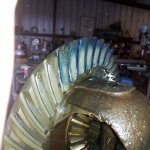
I will add some photos but that is not my forte, so please excuse that they are not captioned. I am happy to correspond with anyone contemplating this job.


Oddly to me, many have overhauled engines and a smaller number have done gearboxes but most folks stop at changing these parts out and take these to a ring and pinion shop or at least someone who has done this before. The BN2 shop manual I have covers both the hypoid type and earlier straight or parallel spiral bevel geared differentials and some of these processes are slightly different between the two, although they both work pretty much the same. I'm only talking about the hypoid gear sets where the pinion is not in line with the center line of the crown wheel as I have in my ‘56 BN2.
There are a few tools that you have to have or make in some cases. I fabricated an axle hub nut wrench as the axle shafts have to be removed and installed to do this as I wanted to disassemble the hubs to inspect and repair as necessary and reseal them when they go back together. You don't need to pull the hubs but it is a convenient time. Since the whole differential carrier assembly comes out of the axle housing, it is convenient to do that yourself and take it to a pro shop and it really shouldn’t be very costly to have someone else do the set up if you choose that route. I spoke to some who suggested it is much easier to remove the whole rear axle assembly and then pull the differential out of the "pumpkin" versus jacking or lifting the car and leaving the axle in place. I elected to jack it and leave it in place as the thought of bleeding the brakes gives me night sweats. Brakes have been flawless since I rebuilt them. If you have good jack stands and they go high enough, with the batteries out and the drive shaft just pushed out of the way, access was pretty easy. In retrospect I would do it this way again if I ever needed to. It was not difficult to remove or reinstall the assembly if done from underneath with the rear end jacked as high as my jack stands would go. I also made a holding tool which picks up the flange of the differential housing when removed so it can be firmly put in a vise. Last, I made a tool that lets me hold the differential coupling flange so the 140 foot pounds of torque could be applied to the pinion nut that holds the flange to the pinion in front. It just picks up two of the 4 bolt holes and I can slide a long pipe extension on it. All done in a 6 inch vise.
The tools you need that you can't make are a good vernier caliper or 0 to 1" outside micrometer, a dial indicator with a magnetic base that is machined flat ( I had a dial indicator with one of those flex neck jointed things that clamps with a vise grip but those are not able to be used for the measurements needed). There is a British tool made for this but the magnetic dial indicator base at Harbor Freight was perfect and inexpensive. Another tool you absolutely have to have is something to remove the inner (rear) bearing on the pinion. The bearing has to come off if you are reusing it and if you need to adjust pinion height. It is installed such that none of my gear pullers or bearing splitter pullers would work without destroying the bearing. I happened to have bought a grab bag of British tooling from a guy years ago and never needed any of it. Low and behold the bearing puller and adapters for this part of the job were among the many tools. They are of a type I had never seen and work elegantly as shown in my photos. They allow pressing the bearing off with no stress on the bearing cage or rollers. Last, you need a special gage block to zero the dial indicator in order to set the pinion height. I also had one of these in my bin of tools. I had always wondered what it was when I came across it in my tooling. All the tools have Churchill or Mowog numbers that are called out in the manual and etched or on data plates on the tools. You could get by with knowing the dimension of the block and machining your own but you need one or the other. The height of the gage block is (surprise!) 1.000 “. If you measure the diameter of the differential support bearings divide it by 2 and add 1.000 ”, if you set your pinion height properly it should equal the number etched or other wise marked on the pinion head. This number is the nominal distance there should be between the center point of the crown wheel diameter and the flat surface of the pinion head, called pinion height. You may have to change the height if you don’t get a useable gear pattern or backlash.
Once you get the picture of what they describe in the shop manual, it is really fairly easy to set the pinion height with the correct shims, the pinion preload with a torque werench able to read 5 to about 50 inch pounds, and the gear backlash. Although they never mention checking the gear pattern I'll be doing that to check everything else. Normally that is the last thing you do when doing this on any rear end and it can be cause to readjust backlash or pinion height.
I should add that all of the bearings and races I could see and feel were pristine and I am not one to replace these just because new is thought to be better. New bearings are not always better in my opinion. I also had no measureable play in any of the gears or thrust washers that drive the axles. The old gears had an excellent gear pattern prior to removal and showed very little wear.
One thing I did notice was some gouging on the differential carrier frame from some previous knucklehead ( me being the current knuckle head) using something evil to hold the assembly during some torque operation. It had been there for a long time and remained except for my dressing the edges.
Unlike more modern set ups, pinion preload is set with shims rather than a crushable spacer. These shims are available from the usual suppliers in a variety of thicknesses, you will likely need a small selection if you are putting in new gearing. The pinion preload is very sensitive to the shimming and one or two thousandths can put you over or under by quite a bit.
There are two other shim types that are not as readily available. The ground shims for setting pinion height were not to be found at a reasonable price or variety of thicknesses. I needed to increase the thickness of mine by .005" so simply got some .005” shim stock and made a shim.
The other shimming you might need to do is for backlash. Interestingly, these shims although they used to be available in a variety of thicknesses are not to be found but are identical to the spacers that are used to pinch the wheel bearing by .004 when you install the axle shaft. Same OD and ID but they are just one of the thicknesses that used to be available. It happens that the ones I had on my axle hub bearings were one of the thickest available so these could be used if one needed some by simply shaving them to the thickness you need. I could have easily made a shim to adjust the backlash but found I didn’t need to to get a final lash of .0085”.
Speaking of setting backlash, many modern cars have threaded plugs on each side of the ring gear carrier bearings and you can tighten one and loosen the opposite to maintain preload on the bearings to alter the position to effect the backlash you want. It isn’t a preload you can measure with a torque wrench, like pinion preload. With the shims on these set ups you have to keep the total shim thickness, adding up both sides, the same to maintain proper preload. There is a procedure which involves using the numbers factory stamped on the bearing mount and measuring the bearing races as described in the manual you must follow if you change these bearings, to have the proper preload. Lucky me, I didn’t have to do this. You would also have to do this if you changed out the ring gear carrier assembly. But in my case, if I had .010” backlash and wanted .008”, all I needed to do was measure my total shims and add a .002” fabricated shim to one side and use some 80 grit wet dry paper glued to a surface plate to shave .002” off the opposite side shim to achieve a .008 backlash. My shims were both well over an eight of an inch thick so this would be fairly easy.
My test drive was a joy. With the W58 Toyota gearbox in 5th using my gps app, at 70 mph on the freeway I was seeing about 2800 RPM and my wife and I could actually talk. Maybe not a real conversation but close.
I will add some photos but that is not my forte, so please excuse that they are not captioned. I am happy to correspond with anyone contemplating this job.
Last edited: