• Hey Guest!
    British Car Forum has been supporting enthusiasts for over 25 years by providing a great place to share our love for British cars. You can support our efforts by upgrading your membership for less than the dues of most car clubs. There are some perks with a member upgrade!

    **Upgrade Now**
    (PS: Upgraded members don't see this banner, nor will you see the Google ads that appear on the site.)
Tips
Tips

Picture of installed OD relay please!

sammyb

Luke Skywalker
Offline
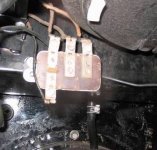
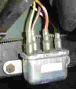
I think my overdrive relay is hooked-up incorrectly (I might even have the wrong one.) Mine has 5 posts, and is not marked with C1, C2, W1, W2.

Can someone please snap a quick picture of their TR3 OD relay under the dash as wired. There isn't a single pic of this on the web, and the wiring diagrams don't help, since they simply refernce the C1, C2, W1,W2 terminals.

Given the OD worked when wired improperly, I'm guessing the relay is wired improperly, since that's the only gray area.

Thanks,
Sam
 
Here's a wiring diagram of the circuit from the A-type Overdrive service manual:

212623-ODdiagram.jpg


-and check your apex email Sam. /ubbthreads/images/graemlins/smile.gif
 
Here's a picture of how my relay is wired right now. As you can see, there are no markings, plus five places to put wires.
 
Here's a picture of the TR6 relay from the Buckeye Triumphs A-type overdrive. Looks a little different but who knows - maybe something will click with you.

At least I'd go on the assumption that the outer poles are the windings and the inner ones are the contacts. Exactly where the wires go on each pair doesn't matter. With a voltmeter you should be able to look for some resistance on the coil circuit and once you've established that you can apply 12volts to the coil and confirm that the other poles are opening and closing.

212712-OverdriveRelay.jpg
 
I keep getting a "Not Found" message for the attachments above, so I'll try to atach a photo of the overdrive relay on my TR3A. It is located under the dash and is held with 2 studs which are located to the bottom left corner of the battery box. These studs are flat-head screws (#10-32 UNF) which are welded through 2 holes in the back wall of the battery box.

Don Elliott
 

Attachments

  • 213007-ODRelay1.JPG
    213007-ODRelay1.JPG
    21.1 KB · Views: 96
Don, thank you very much for posting...I probably should have clarified that I need a picture of the later one -- the one used in post-60,000 cars (and TR4s as well.)

The later one has 5 posts and four wires to go to it. That's why I'm confused!
 
Sammyb

Did you get the picture you needed? I was unable to open all the other attachments as well. I have a pre 60k car but have the new style (post 60K) relay. I will bring the digital camera home from work and snap a few if you still need them?

Harry
 
Harry,
That would be great, as I still don't have a picture of the installed post-60,000 style relay as wired.
 
I seem to have lost my first reply by hitting the enter key by accident so lets try again. The wire color from left to right is as follows-
left front post-Green/yellow rear post closest to engine- no wire!
Brown
Yellow/pink(red?)
white
I would disconnect solenoid just in case your wiring differs so there is no meltdowns. I have post 60K wiring harness as well as rely and couldn't find original but this works for me!

Harry
 

Attachments

  • 213485-TR3Asolenoidrely.jpg
    213485-TR3Asolenoidrely.jpg
    3.3 KB · Views: 80
Sammyb,

I just e-mailed you two of the original pictures I took because the one I posted here became distorted when I reduced it's size. Let me know if you received OK.

Sorry,
Harry
 
My relay was almost identical, except that my brown wire was on the post that you had open (directly above Yellow/Green, rather than one over)

Anyone know if this makes a difference before I go out and fire her up after dinner?
 
Sam,

Whoa, Your braver than I. If you have a voltmeter... set to 50 volts DC, unplug the one wire going to the solenoid and if positive ground connect the black lead of the voltmeter to the single solenoid wire coming fom the switch side of the harness and the other red end probe of the voltmeter to any solid metal part (usually a non-painted bolt on the tunnel or the gear shift lever). Put in any gear other than first, turn key to on position, don't start car engine, flip on O.D. switch quickly on and then off and see if you have 12 volts on the voltmeter. If anything sparks, smokes, or otherwise melts turn the switch off quick! Better yet you really should do continuity checks of the entire harness and gear selector switches connections before actually plugging in and driving away the results may not be desirable if it's wired wrong. If it's negative ground reverse the probes on the voltmeter. If the switches on the tranny need adjustment you will need a manual.

Harry

Otherwise if you get this after the drive I can only hope it worked out.
 
Given Harry's test procedure, I have fire at the solenoid! (not literally, just current, which I didn't before.) I'm assuming that solves my problem, but I'll take it for a spin tomorrow. Have to go give my daughter a bath now.

So thanks Harry. You get four gold stars today.

Basil, can we promote Harry to Yoda status even though he only has 5 posts? /ubbthreads/images/graemlins/wink.gif
 
Just drove it -- yup it works!!! Thanks for the help, y'all. I think I'll give the shop another piece of my mind. ("You charged me for hours spent with a multimeter/test light, when all you needed was the wiring diagram and to plug the wires into the correct posts on the relay.")
 
That's truly good news and I was glad to help! Now if it would omly stop rainng here maybe I can get some driving in as well. Nine days of rain and still counting!
 
Back
Top