• Hi Guest!
    You can help ensure that British Car Forum (BCF) continues to provide a great place to engage in the British car hobby! If you find BCF a beneficial community, please consider supporting our efforts with a subscription.

    There are some perks with a member upgrade!
    **Upgrade Now**
    (PS: Subscribers don't see this gawd-aweful banner
Tips
Tips

TR2/3/3A Overdrive wiring installation

Redoakboo

Jedi Warrior
Country flag
Offline
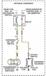
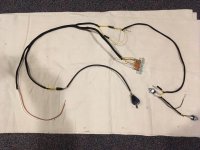
I am finishing up the wiring on my 54 TR-2 I have been restoring. It had been sitting for 30 years and the overdrive wires had pretty must rusted off. I bought a new harness but can't find a good wiring diagram. I have a extra solenoid from my 57 TR-3, I assume will work? and the original relay.

Any helpful hints would be appreciated.

Dick Vinal
 
Randall provides a wiring diagram in this post:

https://www.britishcarforum.com/bcf...gram-1954-TR-2&highlight=Color+wiring+diagram

The relays are the same throughout the range of TR2’s and 3’s. So it should work. The solenoid is designed to mechanically drop the amperage from about 15 amps at activation to only 1 amp to hold the solenoid. The plunger for that feature can become sticky and stop working...so be sure to test the solenoid for amp draw. If it doesn’t trip the contact it will melt within a few minutes.
 
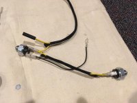
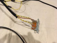
By the way, I'm curious where you found an OD wiring harness? Nobody had one when I was restoring my car. I had to order the "correct" fabric covered wire in proper colors from at least 4 different suppliers, since no single supplier had all the colors. Post #93 starts my OD wiring, which you may or may not find helpful:

https://www.britishcarforum.com/bcf/showthread.php?108693-Recipe-for-a-TR2/page3

If you are interested in adding Randall's diode mod to the relay, I would be happy to explain how it goes. It should extend the life of the relay contacts. I never got around to it, but it's based on solid EE practice.
 
Here's a color OD wiring diagram:
Screen Shot 2020-09-02 at 9.36.20 AM.jpg

John, I believe I got my fabric-covered OD harness from AutoSparks in the UK a couple of years ago.
 
Here are some additional photos showing how the upper and lower harnesses fit together.

IMG_3359.jpgIMG_3360.jpgIMG_3361.jpgIMG_3362.jpgIMG_3363.jpg
 
No way! Britishwiring.com has them
 
...If you are interested in adding Randall's diode mod to the relay, I would be happy to explain how it goes. It should extend the life of the relay contacts. I never got around to it, but it's based on solid EE practice.

Here's how I added that diode that Randall suggested:

X3F5jIp.jpg


I used a double bullet connector to add it in without cutting anything in the harness:

J84wCaF.jpg
 
Geo,

Where did you make the ground connection from the diode?
 
Appending my diode question above, I thought I read that you could also connect the diode between terminals on the relay? If so, which ones?
 
Hard to tell with everything buttoned up but I probably got the ground by running the black wire to one of the two mounting screws for the relay itself.

Randall was much more clever with these things and installed the diode right on the top of the solenoid. I saved a pic of what he did:

efk42iN.jpg


This is the diode I used:

0mcDRQS.jpg


Randall also suggested adding a small fuse to the power to the solenoid... the idea is that it would blow if the pull-in coil ever stuck on (I think that coil draws 20+ amps).

I used an 8 amp Slow-Blow fuse but the pull-in is powered so briefly that perhaps a regular fuse would also work...

Q3lKeqj.jpg


I wired it up with quick connects on each end...

b2NVrSL.jpg


And installed in inline with the power feed to the solenoid:

WDomXRw.jpg


I cannot explain why I mounted the relay upside down.
 
I added a fuse to the solenoid supply and it probable saved the solenoid. It would not always switch over to the lower amp draw and would blow a 10 amp fuse. I found I could bend the contacts in the solenoid to make it work reliable.

David
fuse block.jpg
The heater gets the 15 amp. Overdrive Solenoid 10 amp and the OD relay the 5 amp. The relay that is visible in the photo turns the heater supply off when the ignition is off so I do not come back to a flat battery.
 
Between the plate and slot head screws it looks like what the factory should have done. Very clean installation.
 
I try to work up to Triumph standards.
Don't tell anyone that they are metric screws. What I had on hand.

David
 
Back
Top