Hey Guest!

 Hey - did you know if you click on the title of a thread it will take you to the first unread post since you last visited that thread?
 but were afraid to ask:
  STOP!! Never post your email address in open forums. Bots can "harvest" your email! If you must share your email use a Private Message or use the
  smilie in place of the real @
 Pretty Please - add it to our Events forum(s) and add to the calendar! >>

Offline
This is a follow-up to my previous questions about an overdrive that would not disnegage.
Today I removed the interior and tranny tunnel in anticipation of swapping out the transmisson to a 5-speed later this week.
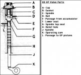
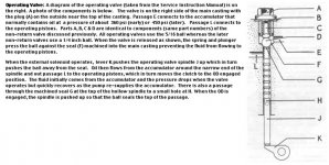
I followed the check out procedure Dave R. had sent. When I removed the valve parts I noticed a definite 'dimple' on the upper spindel where it rides on the ball. There was also a 'dimple' in the underside of the cap screw where the other end of the spindel meets it. The long spindel that rides on the operation cam was clean with no obstruction in the relief hole or hollow center.
After putting the operating valve back together I took the car for a ride. (I made sure there were no loose ends to be caught in the driveshaft) The overdrive worked fine, as it did before, but I didn't drive it long enough to duplicate the previous conditions.
Are the tolerances such that the two dimples could be causing the problem? I don't see how because it doesn't happen until I've driven for 3 or 4 hours. I've had adjustment at the solenoid before but never something like this.
Thanks for your thoughts.
Today I removed the interior and tranny tunnel in anticipation of swapping out the transmisson to a 5-speed later this week.
I followed the check out procedure Dave R. had sent. When I removed the valve parts I noticed a definite 'dimple' on the upper spindel where it rides on the ball. There was also a 'dimple' in the underside of the cap screw where the other end of the spindel meets it. The long spindel that rides on the operation cam was clean with no obstruction in the relief hole or hollow center.
After putting the operating valve back together I took the car for a ride. (I made sure there were no loose ends to be caught in the driveshaft) The overdrive worked fine, as it did before, but I didn't drive it long enough to duplicate the previous conditions.
Are the tolerances such that the two dimples could be causing the problem? I don't see how because it doesn't happen until I've driven for 3 or 4 hours. I've had adjustment at the solenoid before but never something like this.
Thanks for your thoughts.