Hi Geo,
Don's info is good, but I think the TR4 w/OD uses a slightly different gearbox cover than TR3 w/OD, so let me jump in here with some suggestions.
You can opt not to add *some* of the access holes, but that would normally mean completely removing the gearbox cover to do any service work on the OD (see below for a possible solution).
The RH side cover, however, also provides extra room for the angle drive and/or speedo cable (early cars just used a longer cable without an angle drive). The location of the speedo connection is different on the OD than on the non-OD box, so that side cover not only gives access, it is "bumped out" to make for some clearance in there. The angle drive does need occasional service, it will fail if not kept lubricated with some grease.
Last I looked, those RH side covers aren't available anywhere. One sold for a lot of $$$s on eBay recently. It might be possible to fabricate, but would need some experienced body hammer work to make it look anything like the press-formed original.
The LH side has a flat plate access cover that's there to give access to the OD adjustments and solenoid. This one is pretty easy to fabricate out of any available flat sheet steel or aluminum. However, it's positioned right under the LH leg of the dash support yoke and not very easily removed without pulling out that support (I'll get to more about this in a minute). It also doesn't give very good access to the solenoid.
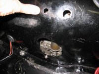
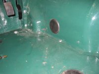
Another hole is on the RH side, above the socket/cap, inside which the OD actuating valve is fitted. This is where a pressure gauge needs to be fitted during some servicing, so is intended to give access. The hole is approx. 1-1/4 round with a rubber plug.
The last hole (if memory serves) is up near the firewall, at about the 1 or 2 o'clock position, approx. 1" diameter fitted with a rubber grommet for the wiring harnes to come through.
But, all this is only academic unless you are seriously worried about originality in an area no councours judge will ever see. The only real practical consideration is creating a "bump" to allow some clearance at the angle drive/speedo cable connection. For example, if using a polyurethane cover, it might be possible to heat it up carefully and shape it to form that clearance bump.
IMHO, another solution is a two-piece cover. One of the British vendors (I forget which... maybe Racetorations) offers these in fiberglass, but I think one would also be pretty easy to make one out of the widely available polyurethane covers being offered by some vendors.
Essentially, the two piece gearbox cover is sawn in half right at the TR4's dash support yoke, and has some sort of fastening and seal added there. This allows the rear half to be removed while the front half of the cover stays bolted in place. To my way of thinking, this is the ideal solution - especially for an OD-equipped car - and will give best/easiest access to everything. In this case the only other mod that would still be needed is the clearance bump at the angle drive/speedo cable connection.
I plan to modify one of those covers this way. I'll use a flat piece of aluminum inside to form a flange that the rear half bolts to, probably riveted/glued to the front half of the cover. That arched piece of aluminum will also act as a support to help prevent the polyurethane from ever sagging if it gets warm (I suspect this might be a problem with a two-piece cover, the one piece cover is pretty rigid and self-supporting). I think 1/16 or 1/8" x 1-1/2" wide aluminum will work fine.
Regarding solenoids, I've got an original in my car that works fine when tested, we'll see if it continues to work well when the car eventually goes back on the road.
The main "killer" of the A-type's operating solenoid is mis-adjustment of the OD linkage. This is becasue the solenoid uses two separate circuits: One is a higher powered circuit that's for the initial actuation, i.e. for the first movement of the solenoid's plunger. The other is a lower power circuit that then switches in to hold the plunger and the OD linkage in the "on" position, until the power is cut off, the linkage is returned to it's resting position and the OD is disengaged.
If adjustment of the linkage is off a little bit, the high power circuit can stay engaged all the time. This will *greatly* shorten the life of the solenoid.
The method of adjusting the linkage "by the book" is to use a 1/16" drill bit to align a hole in the OD case with a hole in the linkage, both located on the RH side of the box (opposite the solenoid and accessible through that cover we discussed already). The linkage is then adjusted by loosening the actuating arm and rotating it a little on its shaft. This works well, if the OD is in like-new condition internally. However, the problem with following this method is that if an OD has some wear and tear on it, such as on the clutch surfaces, this method is unlikely to be very accurate and can leave the solenoid working harder in the high power mode all the time. A better and more accurate adjustment method is to remove the cap from the valve on the RH side and use a dial inidicator to measure the exact amount of lift the linkage is giving to the ball in there, moving it up off it's seat to allow hydraulic pressurization of the OD unit. I don't have the exact figure at hand, but it's in the service manuals. With the adjustment set this way it should allow the solenoid to drop back into the low power "hold/on" mode right after the initial high power actuation. Still, it's worth double checking carefully at the solenoid that this is happening.
Hope this helps!
/ubbthreads/images/graemlins/cheers.gif

 Hey Guest!

 Hey - did you know if you click on the title of a thread it will take you to the first unread post since you last visited that thread?
 but were afraid to ask:
  STOP!! Never post your email address in open forums. Bots can "harvest" your email! If you must share your email use a Private Message or use the
  smilie in place of the real @
 Pretty Please - add it to our Events forum(s) and add to the calendar! >>