• Hi Guest!
    You can help ensure that British Car Forum (BCF) continues to provide a great place to engage in the British car hobby! If you find BCF a beneficial community, please consider supporting our efforts with a subscription.

    There are some perks with a member upgrade!
    **Upgrade Now**
    (PS: Subscribers don't see this gawd-aweful banner
Tips
Tips

Nial - front suspension link triangulation

RobSelina

Jedi Warrior
Offline
Nial, do you have a pic of that suspension arm you fabricated to triangulate the lever arm? Couldn't find that thread for the life of me.

I was picking up some parts from McMaster and decided to get some heims and hardware to make a similar set of links. Figure I might as well take a good look at how you did it first, no reason to reinvent the wheel.

BTW, also ordered everything I need to make heim jointed sway bar links and replace my tube shock conversion nuts and bolts with grade 8 hardware.

Should be fun!
 
Sure!

Probably the picture you are thinking of was the one where the upper shock mount had torn after (bumpy) Lime Rock. You could see the added link in that photo. It's here:

https://img.photobucket.com/albums/v170/aeronca65t/Cars/sprite-shock.jpg

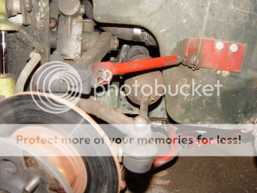
A better picture of the added triangulation link can be seen below.
The trailing arm itself is about 5/8" OD steel.
It is around 7.25" from center to center of the rod ends.
It would have been neater if I had a LH thread for one end but I didn't have a tap handy, so I need to take one end off to lengthen or shorten the arm. Not a big deal since it really hasn't changed any.
Be sure that the arm moves up and down without binding. It's better to disconnect the lever am and move it up and down without the king pin to be sure of this.
The lever end is attached to the arm by a piece of 1" by 3/16" steel that is roughly like an "S". This steel piece is held to the lever arm by the exisiting pinch bolt and the through-bolt. The plate on the other end is 2" by 3/16" and it is bent out at roughly a 30 degree angle. It's bolted to the car and also glued (with PL200 construction adhesive).
Remember that this can only be done on rubber bumper Midgets, but not earlier Spridgets (because the metal that the trailing arm attachs to does not exist on older cars.....it's part of the bumper reinforcement area). You might be able to add some material to an older car or add an arm behind the lever. Not sure.
The main benefit I have found is during heavy trailbraking from high speed. Before I added this, the car would move around under hard braking, sort of steering itself. I drive another Mk1 Sprite that runs large and very sticky bias Hoosiers and it's even worse. After this, the car is much more stable under hard braking during turn-in (my car has Carbotech pads and Brembo rotors but just stock calipers).

I need to improve my sway bar links with heim joints too....right now my setup is pretty agricultural.

Have fun!


suspension.jpg
 
Thanks Nial.

I was planning on doing double shear mounts at the body, but looking at yours, it will be unecessary. At the lever arm, I was planning on using the trunion bolt, but didn't think to also use that tension bolt on the front too, good idea.

About the only thing I might do differently, is bring the mount upwards a tad, so that the pivot at the body is level with the lever arm pivot. This should prevent any binding problems.

Thanks for the pics and the tips!

BTW, think I'll have a brake setup very similar to yours shortly. I ordered replacement Brembo rotors and hawk pads (along with an MC kit, caliper kit, rear drums, shoes and cylinder kits). We'll see how that pans out.
 
Yeah...as I look at it, I think the mount should be higher too. I don't remember why I chose the present location.

I ran the Hawk pads previously and the set I had was very loose-fitting in my calipers. At one point last year, one of them spun 90 degrees in the caliper (they were worn about 1/2 way down). Not sure if it was just a fluke, but check the fit when you get them.
 
Rob......

before you start whacking and cutting you might want to do some stickmen and cutouts.

The triangulation pieces can be made full scale with sticks of wood and posterboard and string.....you will find that unless you do these struts properly that you will have a binding issue when traveling the suspension. The length and location of the added front strut are critical to eliminate binding.

The better attachment point of the added strut is to the rear with brackets in double shear. But then if you were adding tube shocks they would be in the way.
 
yea, tube shock is already behind the lever arm so that won't work. I'm planning on mocking up the mount with the new arm before drilling it. Make sure it's a good location.

I received my pieces from McMaster today, should start fabrication tonight if all goes well!
 
Peter May engineering makes a kit that does this as well but from the other side of the trunnion so it kinda make a arm aroud the shock, Thats whats on my SCCA race car, it's a bolt up.
 
thought I'd post up a conclusion to this:

I built the links and brakets, basically look like Nials but they did not work out for me. I had them attached to the lever arm only while everything else was apart and it would bind. didn't have more than about 1" of travel.

I see the error in my ways and really need to just get a top brace like the peter may one Hap mentioned. It's mirrored to the lever arm so it won't bind....
 
Hmmm? Too bad.
Wonder what happened?
Mine will drop from full up to full down with no binding (well OK...a tiny amount at full down, but not something that creates any real friction).
I like the Peter May design (plus it will work on older cars)....I'll be interesting to hear how it works out.
 
I can tell you what happen with the bind or a good guess anyway. The Peter May kit is how I described above and the add-on link is perfectly in line with the shock arm on the other side. Your set-up Nial, while not perfectly aligned with the shock arm is close enough that bind did not occur withing the travel of the suspension. Anytime you put multiple pick up points and links at different locations on a suspension that travels in a arc motion,if bind is beyond suspension travel you shouldn't bind, but if locations are too drastic they will bind before suspension travel is reached. Peter May's kit is not only in line with the pivot point on the shock arm but also is the same length, so it's almost impossible for bind to occur. Nial if you disconnect your king pin assembly and pull it out of the way and move your shock and links up at down you should be able to feel bid at some point due to the different angles.
 
Back
Top