• Hi Guest!
    You can help ensure that British Car Forum (BCF) continues to provide a great place to engage in the British car hobby! If you find BCF a beneficial community, please consider supporting our efforts with a subscription.

    There are some perks with a member upgrade!
    **Upgrade Now**
    (PS: Subscribers don't see this gawd-aweful banner
Tips
Tips

Metro 1500 Has Slack Timing Chain?

doc50

Jedi Trainee
Offline
Greetings again.

My new to me '58 Met seems tight, no smoke, but even after adjusting valves (.015) there is a 'Singer Sewing Machine' clackety sound from the very front of the motor. I took the oil fill cap off and the valves are nice and quiet. It's all from the front, and the idle constantly searches. I don't think it's the carb, because the changes in RPM are about every 5 seconds, up and down, up and down.

Am I circling the right diagnosis, a loose chain/tensioner?

I'm not professional mechanic but I have rebuilt several engines and I can't think of anything else that would make that noise and I know valve timing changes would affect the idle.

New developement: The crank bolt is stuck. Does anyone have a real neat way to cajole it? I'm thinking of heating it till red hot, letting it cool a couple minutes and go for it. Please stop me if that's a very bad idea...

Thanks.

Thom
1958 Nash Met 'Chuckles'
1973 MG Midget 'Midge'
 
Last edited:
A slapping timing chain makes a pretty distinct sound. In my experience, it's not a ticking but a pretty significant rattle. Putting the tip of a long screw driver on the timing cover and holding your ear to the handle end while the engine is running is a good substitute for a stethoscope. That will let you pinpoint the cause of the noise.
A worn distributor will also let ignition wander, which could change the RPM.
As to the stuck crank bolt, is there enough room to get an impact gun on it? Baring that, I use a wedge or pry bar to hold the engine at the flywheel and put a breaker bar and extender pipe on them when needed.
 
Took the front stuff off today, wish I'd read your reply when I could have used that method to isloate the noise
Amazingly, the chain / tensioner seemed to be the best shape of all!
1) Water pump flange was in 2 pieces
2) crank pulley had all rivets loose, pulley itself was bent. I'm thinking that the 'Singer Sewing Machine' sound from the front of the enginewas from the crank pulley's wobbling.

Tried the 'use the starter method to break loose the crank bolt, not enough torrque. Got bolt off by heating till red, came off like butter. Onward!

Thom
 
I agree to listen for the noise using a stethoscope or screwdriver. Mechanic's stethoscopes are available from Harbor Freight and they do work.

I would not heat the crank bolt unless you exhaust other options. The air impact gun is a good option if available. Just make sure that you have the air pressure turned all the way up and the torque on the gun adjusted all the way up.

There is an alternate to the impact gun that some people use on engines that rotate clockwise when you look at the crank pulley. Place a 6-point socket on a breaker bar. Place the socket on the crank bolt and wedge the breaker bar handle against the frame or other convenient hard spot. Then pull the center lead off the dizzy cap (so the engine cannot start) and bump the engine over on the starter. This lets you use the starter motor's torque to break the bolt free. I have not watched all of the video linked below and I have listened to none of it. However, starting around 40 seconds and ending at about 1 minute 20, the guy does show the technique I mentioned above.

https://www.youtube.com/watch?v=7G-adEVjfWI

 
Tried the 'starter as torque provider' first, did not work. (I think the starter's weak, so I will try to figure out a stress test for it).
Heat was my last resort and it worked well.
Thanks for the input, Doug. I'll watch the video.
Thom
 
Do a little Google searching before using heat. Some BMC engines (and I CANNOT confirm this applies to your 1500) have harmonic balancers on the crank. Those are made from steel parts bonded together with rubber. Obviously the 50 year old rubber will not take the heat well.
 
I wouldn't use heat on it. Have you considered getting an electric impact?
 
Harmonic balancer was bent, rivet holes were slotted, so I didn't care. Heat worked very well....like butta...

The space was too short to fit my air impact wrench, or that would have been my first choice.

Any ideas about how to bench stress test my starter? I think it's weak.

Thanks,
Thom
 
The only way I know to test a starter is to see how much current it's drawing during cranking. It needs the resistance of spinning an engine to make it work hard enough to draw full starting current, and you'll need a way to measure current draw up to ~400A to see if it's weak or failing.
Once it's up and running, any local shop should be able to hook and amp clamp up to the main feed to the starter and see what it's drawing while cranking.
Is it sluggish to turn the engine over with a known good battery?
 
Thanks, 'Alfred'. I'll check with a shop. Yes, I have a known, strong 27 series batt and it bogs on start up about 90% of the time. I haven't checked timing, maybe it's way too advanced.

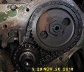
Another thing, I attach a pic of the timing chain and tensioner. Do you know how to check to see if the chain is stretched? The tensioner looks like it way out of it's normal place of rest. The pic shows tensioner to be about 1/2'' in extension. Too much?

Thom P1020678.jpg
 
More questions than answers right now:
1) Can someone tell me how to install the felt crankshaft seal in the timing cover? It looks like I have to worry it into the slot, then perhaps finish up by closing the slot slightly with a big socket?
2) Is timing done with a light using the low timing cover tab with the 3 pointers?
3) How to tell if PO set the dizzy in correctly? In other words, where does the rotor face if shaft is correctly?

Thanks.

Thom
 
You are rapidly moving into areas I cannot answer about the 1500 B-Series.

I will offer the following. The long pointer on the timing chain cover is TDC. The two others are 5 and 10 BTDC. Regardless of what the final dynamic timing should or could be, you can set the static timing for about 8 BTDC (eyeball it) and the engine should start reasonably well. Dynamic timing can be set later. Are you already familiar with how to set static timing?

The rotor position on the B- and A-Series engines should be similar. With #1 at TDC on its firing stroke the rotor should be pointed somewhere between 1:00 and 2:00 o'clock. This will have the vacuum advance module pointed almost straight up. If necessary you can remove and re-position the dizzy drive gear in the block to get the rotor pointed where you need. Are you familiar with how to identify when #1 is at TDC vs #4 at TDC?
 
Thank you, Doug, for your follow through.

To address your post:
1) I have forgotten how to static time. Please, if you would, go through the steps.
2)'' Are you familiar with how to identify when #1 is at TDC vs #4 at TDC?'' No. Again, I'd appreciate it if you could tell me how to differentiate those.
BTW: Looking at the cam and crank gears, when the dots are lined up, is that always when #1 is TDC?

Thanks,

Thom
 
Rather than provide the entire static timing process here I direct you to the website linked below where I store various documents. Look for and download the PDF document about static timing.
https://sites.google.com/site/purlawson/home/files

To identify when you have #1 at TDC on its firing stroke carry out the following steps.
Mark/number the spark plug wires and remove them.
Remove the spark plugs.
Remove the valve cover.
Temporarily refit the crank pulley you just removed.
Place the car in neutral and turn the engine over by hand in its normal direction of rotation.
Watch the timing pointer and pulley.
Stop when the long pointer and pulley notch are aligned.
Turn your attention to the rocker arms above cylinder #1. Grab the arms and try to wiggle them.
If the arms are loose and can be wiggled, you have #1 at TDC on its firing stroke.
If the arms are tight and cannot be wiggled, you have #4 at TDC on its firing stroke. Turn the engine over one more complete revolution and check the rocker arms again. You should now have #1 at TDC (#1 piston up, rocker arms loose).

When you set the static timing, turn the crank BACKWARDS by about 30 from TDC. Then SLOWLY pull the engine forward again in the normal direction of rotation. This takes all the backlash out of the system. Stop when the crotch between the two short timing marks is aligned with the pointer. That's going to be about 7.5 degrees BTDC. Good enough for starting.

However, if when you have #1 at TDC you find that the rotor is not pointing to about 1:30, now is the time to change the drive gear position. With the engine sitting at #1 TDC, remove the distributor. Find a long 5/16-24 bolt or perhaps a long stud. Thread it into the drive gear and then use it as a handle to remove the gear from the block. Re-fit the drive gear in a new position as necessary so that the dizzy rotor is pointing to about 1:30. Then go through the steps in the document to set the static timing.
 
I appreciate your taking the time to go through this. It helps me immesely.

Just printed out your article on 'static timing'. You created what I think is the clearest and most comprhensive set of instructions I've read yet. I will refer to your other articles as needed. Thanks again.

Thom
 
Anytime Thom. If you need anything cleared up, post here or send me a PM.

Be sure to post how you are progressing.
 
Roger, wilco. I notice you're living in the vicinity of the 'Can Opener Bridge'. (Don't truck rental companies have special instructions??) Many chuckles from seeing those videos! Our 1971 Revcon would just barely fit!

Thom
 
Fortunately I live in the SW corner of Durham and that bridge is very close to the center of downtown. You would think that by now enough warnings in advance of the bridge would stop the collisions and accidents. My wife used to work in downtown Raleigh near the Peace Street bridge. It also claims a lot of trucks, usually semis.
 
Both bridges long pre-date the larger trucks of today. Since both bridges involve railroad beds, it is not a trivial task to make the bridge taller.

For those curious about the canopener bridge, it is a rail bridge in downtown Durham, NC. The clearance for cars and trucks is 11'-8" and that routinely results in box trucks peeling off their roofs. It has been on several episodes of Tru-TV and there are multiple YouTube videos showing many of the accidents. See below.

Nearby Raleigh has the Peace Street bridge. It is also a railway bridge and it has a clearance of 12'-4". Box trucks seldom have a problem with that bridge but semi trucks routinely get half way under when the slope changes and pins the trailer under the bridge.

Canopener

Peace Street (there is no webcam so videos like this are from local news stations and filmed after the fact)
 
Back
Top