• Hi Guest!
    You can help ensure that British Car Forum (BCF) continues to provide a great place to engage in the British car hobby! If you find BCF a beneficial community, please consider supporting our efforts with a subscription.

    There are some perks with a member upgrade!
    **Upgrade Now**
    (PS: Subscribers don't see this gawd-aweful banner
Tips
Tips

Lost 8 terminal Flasher Relay Plan

Steve,

No. The bilge blower was installed next to the foot well to hide it. Until I install a closed sided duct between the radiator and grill with a smaller branch duct leading to the cold air intake, the bilge blower is worst than useless on a Summer day at a traffic light. Eventually I will create that closed radiator air duct and be able to go back to the original yellow mettle fan with the engine staying cool on the hottest Summer day.

Ray(64BJ8P1)
 
Last edited:
Hi All,

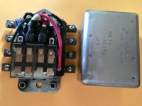
I finally completed the re-built of the DB10 Flasher Relay box and initial car testing shows that it works. Although the longevity of this implementation may be shorter then the 54 years of the original, replacement of the two $4 relays should be reasonably quick and relatively easy and, differing from the original, will not require any points adjustments.

I must admit that the implementation was laden with multiple frustrations caused by the fact that local parts sourcing is gone and on-line components acquisition takes time. Yes, the instructions do help identify what is required, however, they are less then complete and you always find additional things not mentioned. For example, I acquired the 10-32 rivet nuts on line but could not find a local source for a hex-head 10-32 bolt for their installation, or when determining that an 1/8"x3/8" steal pop rivet would be the most appropriate size to re-anchor the box base connectors, after visiting multiple Home Depot and Lowes, I had to settle for 1/8"x1/2" and use my Dremel cut-off for proper fit, etc. My advice, order everything on-line at the same time...but then you would need to know all that is required. By the way, due to the limited space, Steal pop rivets were selected over aluminum rivets to facilitate soldering of in-box wiring leads.

However, when finally getting my Healey back together, all frustrations and aggravations of the build will be forgotten and I will just enjoy the fruits of the labor (hopefully). Hear are a few pictures of the implementation.

IMG_E0107.jpgIMG_E0145.jpgIMG_E0153.jpgIMG_E0154.jpg

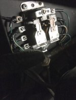
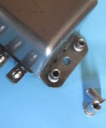
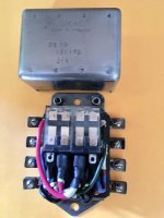
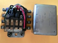
The first picture is of the original Flasher Relay Box. Picture 2 is of the 10-32 Rivet Nuts installed to allow demounting of the upper 2 box mounting screws from the wheel well rather then removing the cold air duct (which requires the removal of the fender/door. Picture 3/4 shows 2 8-port DPDT 12V 10A Relays, with wiring, mounted to fit in the original box.

Ray(64BJ8P1)
 
Last edited:
Good work!!

I threw together a replacement relay using Radio Shack relays a couple of years ago when I needed one on a day's notice, but it didn't fit into the original box. I've since replaced it with the Moss unit, but keep it as a spare. Maybe I'll rebuild it like yours.

BTW, what is Attachment 54366? A click says it's invalid.
 
Hi All,

UPDATE:

Although no Double Pole Double Throw 8-port DPDT 12V 10A Relays are rated for Automotive use, the small relays used in the Flasher Relay box (Lucas DB10) rebuild are performing nicely and my rear lights seem brighter as a result of the new internal points/triggering-components. However, there are 2 longevity factors to consider when mounting these highly complex sealed relays that were either addressed when mounting or will be considered.

IMG_E0154.jpg

Factor 1 to consider is vibration and shock that could cause the internal components of these relays to dislodge and malfunction. To this end, I have not glued the 2 relays to the base but placed them on the insulator, framed and contained by the external rivets and held down by a small piece of rubber tubing placed across both relays that applies a small amount of pressure on the relays when the cover is installed. In the event of a hard road jar, the relays will be able to move slightly while still maintain position and operation.

Factor 2 relates to diminishing the power across the internal DPDT relay's points. Although the relays used in the rebuild are each rated to handle 10 amps at 12Volts DC, well under the turn/brake signal power draw requirement, I am considering the benefs of installing 2 additional 4-terminal Automotive Rated power relays at the rear of the Healey to provide direct bulb power for Brake/Turn Signals. As I see it, this would diminish power passing through the Flasher Relay Box relays to that of external relay-triggering amperage for rear signals along with only amperage for 1 front Turn Signal light.

All in all, time will tell if this rebuild would be as substantial as that of the original unit's 54 year longevity.

Thoughts would be appreciated,
Ray(64BJ8P1)
 
Last edited:
Rebuilt mine using Jean Caron's instruction document (see John Turney's link above) with the eBay relays shown above. Used 18 ga stranded wire and 1/8 x 1/4" steel pop rivets and 4.8mm female spade connectors. Foam holds relays securely when cover's in place.

Edit: Installed it and can report it works perfectly - like Ray above, I think the lights are brighter:

screenshot.1979.jpg


screenshot.1976.jpg
screenshot.1978.jpg
 
Last edited:
Bob,
Search for spade terminal, crimp terminal or terminal kit on Amazon, eBay and Walmart.com. Interestingly Walmart has a lot of electrical supplies. Here's a typical kit. These kits are all over the above sources. I only buy the factory-style double crimps. British wiring also sells the connectors on a per each basis - but maybe not the clear sleeves.

screenshot.1980.jpg
 
I've bought many crimp tools, but mostly use this modified simple one from British Wiring. It's important the upper part has the curved downward point - this enables the proper crimp. See the slot closest to the pivot.

screenshot.1981.jpg


I ground the back part of the tool down in order to make the front close tighter.

screenshot.1982.jpg
 
Thanks. I've got a couple of ratcheting crimpers, which I like, but I haven't been able to find connectors that crimp both the stripped wire and the insulation, which I think is the most robust type. Still looking, no luck even from the 'marine' and 'aviation' suppliers.

I like the 'compound' stripper, like this one (mine doesn't have the cutter, though):

https://www.amazon.com/Stripper-Electrical-Klein-Tools-11063W/dp/B00BC39YFQ


Edit: Looks like the ones you posted could do the trick, but I think you need crimper anvils the fold the tabs over (other type is like a tube, that just gets squished).
 
Those Klein strippers are incredibly useful. Highly recommended for auto and around the house.

I'd recommended the crimper above because I didn't have a good technique for the racheting crimper (needed three hands). Someone online mentioned you insert the terminal in the tool and tighten it just enough to hold the terminal, then insert the stripped wire and finish the job. This works well.

There are a number of sets on Amazon which include the crimper.

One Amazon reviewer liked the clear boots - he said they looked like the OEM clear boots on old British cars.

screenshot.1984.jpg
screenshot.1985.jpg


Sample from above crimper, 18 ga wire:

screenshot.1988.jpg


screenshot.1983.jpg
 
Last edited:
Hi All,
Although I can appreciate crimping wiring ends could be easier, I still prefer soldering ends and feel this method would provide a more resilient and long-term secure connection than that of a mechanical crimp. I use the same ends and end-covers as used by those crimping them on and also find a soldering iron to be easer to work in tight places. So why would you use a crimp on this or other connectors within your Healey?

Just my thoughts,
Ray(64BJ8P1)
 
When I was an active pilot, I subscribed to a publication called 'Light Plane Maintenance.' This mag was subscriber-supported and did not accept advertising so the writers and editors 'told it like it is,' and most were certified Airframe and Powerplant (A&P) technicians and some of them had Inspector Authorization (IA--the people who decide if mods and repairs were done properly, Airworthiness Directives were complied with and the aircraft was fit to fly). Many years ago, they did a study on the best way to make electrical connections and found, for various reasons, that a properly done crimp connection was superior in several aspects to soldered (sorry, I don't remember the exact details). The connections had to be done properly, of course, with professional grade tools and aircraft grade connectors. IIRC, the main issue with soldered connections was that 'cold' joints were easier to create than to detect.

Seeing that reliability is somewhat of an issue in aircraft I was inclined to accept their recommendations.
 
I've almost always used crimping after reading an earlier posting by Bob of similar info to that above. I also like soldering in some cases - with reinforcement. Soldering is brittle at the joint where the wire enters the solder. A few bends and these wires would break off:

screenshot.1989.jpg


I like to use heat-shrink tube as a strain relief as well as insulation:

screenshot.1990.jpg


A properly-done double crimp also provides strain relief:

screenshot.1988.jpg
 
Thanks Guys,

Although I have used crimping on a few things in the past, I always felt a mechanical pressure connection to be inferior and susceptible to corrosion via moisture penetration. A soldered connection is a sealed conductive connection and would not be open to moisture penetration. As far as assuring a good solder connection, I believe this is no different then assuring a good crimp as it requires careful performance of the uniting procedures. I do not see the strength of the soldered connection to be an issue as I would be using the joint in an electrical circuit and not in applications placing stress on the union. If there were to be a section that experiences movement and stress, I would assure that the movement were maintained by the proper selection of wire and anchor the wire and not depend on securing via the union.

Just my thoughts, However, I do now have greater respect for a crimped union so thank you,
Ray(64BJ8P1)
 
The LPM guys generally go 'by the book;' i.e. FAA AC 43.13, the "A&P's Bible." It's online--646 pages--here:

https://www.faa.gov/documentlibrary/media/advisory_circular/ac_43.13-1b_w-chg1.pd

Relevant entries start at page 11-67. I always figured if it's good enough to keep an aircraft in the air it's good enough to keep a Healey on the road.

Pre-insulated crimp-type ring-tongue terminals are preferred. The strength, size, and support*ing means of studs and binding posts, as well as the wire size, should be considered when determining the number of terminals to be at*tached to any one post. In high-temperature applications, the terminal temperature rating must be greater than the ambient temperature plus current related temperature rise. Use of nickel-plated terminals and of uninsulated ter*minals with high-temperature insulating sleeves should be considered. Terminal blocks should be provided with adequate electrical clearance or insulation strips between mount*ing hardware and conductive parts.
 
Back
Top