• Hi Guest!
    If you appreciate British Car Forum and our 25 years of supporting British car enthusiasts with technical and anicdotal information, collected from our thousands of great members, please support us with a low-cost subscription. You can become a supporting member for less than the dues of most car clubs.

    There are some perks with a member upgrade!
    **Upgrade Now**
    (PS: Subscribers don't see this gawd-aweful banner
Tips
Tips

TR6 Looking for some TR6 wiring connection info

Dennis

Jedi Hopeful
Offline
Hi,
I was the one who purchased the TR6 by way of Mickey. Due to the weather this summer ( or lack there of )and trying to get my GT6 carpeting project finished, I wasn't able to do much of anything on the TR6. But with the GT6 in storage I have plenty of room to work on the TR6, I've made good progress.
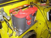
I've had the oil pressure pumped up, we won't talk about what I didn't check before hand. I've got a lot of the wiring hooked back up. At this point I need some help with what actually goes to what and what does it look like.... One the firewall next to the positive side of the battery, I have 3 spade connectors with brown wires that attach to something..
Just not sure what that something is, schematic makes it look like some kind of terminal block but I'm just not sure...
If someone could describe it or take a picture of it and post it somewhere, I would really appreciate it...
Thanks!
Dennis

ps. If all goes well, I hope to be able to try and start it for the first time this weekend...
 
Dennis..........the first thing I'd suggest is that you go to the AAW site and download their free set of wire schematics for the TR6 . These diagrams are the best and most accurate available and will probably answer most of your questions.

The brown wires are all associated with the starting circuit but I don't recall there being any kind of a terminal box mounted on the firewall by the positive terminal. I wonder if the PO removed that big funky block built into the positive cable and replaced it with the terminal block. It's #30 in the Moss diagram.
 
Well, there is a ground spade that is on that side as shown here, but the brown wires go to the starter and the black smaller wires go to ground.
 

Attachments

  • 19614.jpg
    19614.jpg
    89.8 KB · Views: 342
DENNIS! Good to hear from you!

I'm on pins and needles here, waiting to hear it fire off!

:cheers:
Mickey
 
Originally it was attached to the Positive battery cable. Take a look in the Moss catalog in the "Electrical" section. But you can modify the connection such as the PO did. OR look up the Roadster Factory part #159805 or 517081; it's one of the two.
 
Good, thanks folks. The schematic showed them as connecting to the battery cable in some way. Paul's picture shows 2 of the brown wires, the 3rd one is down a little farther on the harness. The black wire and WR were easy enough to figure out. But the 3 spaded brown wires had me baffled. I'll have to try and post a picture of it tomorrow. I have a few other questions as well.
Thanks!
Dennis

Sorry Mickey, hopefully this weekend!
 
BobbyD has it right. The 3 brown wires connect to the terminal block that is attached to the positive battery cable.
 
Dennis said:
Good, thanks folks. The schematic showed them as connecting to the battery cable in some way. Paul's picture shows 2 of the brown wires, the 3rd one is down a little farther on the harness. The black wire and WR were easy enough to figure out. But the 3 spaded brown wires had me baffled. I'll have to try and post a picture of it tomorrow. I have a few other questions as well.
Thanks!
Dennis

Sorry Mickey, hopefully this weekend!

Bated breath here.

I emailed Allison; she's pleased you're making progress. I have to believe that Bill would be, too.
 
The Schematics were the first things I downloaded, couldn't live without them! It's gets to be a little challenge not knowing what things looked like and of course things have to be so different from the Spit and GT6. I've been lighting things out and checking for shorts, so all should be well there. ( The only smoke I want to see is from the MMO I put into the cylinders when it fires up! )I currently have 1 little oil leak coming from around the banjo bolt of the external oil feed that goes into the head. I will probably remove it for now and put a plug into the block and the bolt back into the head for now. I'll get a new set of copper crush washers and see if I can't reinstall it later. I'll order the proper battery cable needed and work around it for now. ( again thanks for the help!! )
I'm with you on that one Mickey, I just can't wait to hear her fire up. If the weather is good on Sunday, I'll roll it out of the garage. If not I'll just open the door. Hope all is well with Allison and Seth, I still need to figure out what I'm going to do for a little memorial for Bill on the car but all in due time.
Dennis
 
Dennis said:
I'm with you on that one Mickey, I just can't wait to hear her fire up. If the weather is good on Sunday, I'll roll it out of the garage. If not I'll just open the door. Hope all is well with Allison and Seth, I still need to figure out what I'm going to do for a little memorial for Bill on the car but all in due time.
Dennis

Let me know if I can assist. Would be an honor.
 
Dennis referring to Broski's picture, this is the spot the tr6 needs a fuse block added to protect the(IMHO very poorly protected)main harness.Bring a heavy gage wire off the poss cable to power the block then plug in the brown wires to it and install 30 amp fuses.The factory put no fuses into these main power wires and many a dash fire was the result.....The VTR does NOT count off at concourse for well done safety mods.I do it on any late 6 that goes through my shop.
MD(mad dog)
 
Hi MD,
Thanks for the suggestion, I'll take it and make my own little wiring harness with a fuse block.
Dennis
 
The beauty of it is that you only need the block and a power wire to come to it. The brown wires then plug into the spades on the block.The car has not really been altered and its much safer.
MD(mad dog)
 
Hi,
Finally have the picture and the second question. In the lower portion of the attached picture is a strain relief that goes through the shelf. What exactly goes through there? I can't seem to find a missing wiring harness or any reference to it..


location_question.jpg


Thanks,
Dennis
 
Back
Top