• Hi Guest!
    You can help ensure that British Car Forum (BCF) continues to provide a great place to engage in the British car hobby! If you find BCF a beneficial community, please consider supporting our efforts with a subscription.

    There are some perks with a member upgrade!
    **Upgrade Now**
    (PS: Subscribers don't see this gawd-aweful banner
Tips
Tips

Generator - Key Replacement

gonzo

Jedi Warrior
Gold
Country flag
Offline
Hello All,

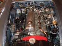
Considering replacing generator with a dynamator - a Lucas C40 style alternator - on my AH 3000 BJ7 and have a couple of questions:

1. The generator's nut, pulley, fan and woodruff key are all transferred on to the Dynamator. Is the woodruff key (no. 19 illustrated below) readily available from a well stocked hardware store? And if so, what are the dimensions?

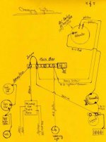
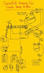
2. Alternator conversion require re-wiring and a choice to "gut" and modify the Voltage Regulator so that it could be used as a junction box for original wiring. Coils and resistor, from the backside, should be removed. But how are the isolated terminals then modified or "jumped" to keep original wiring locations to A1, A, F, D E terminals functional? I'm trying to avoid bunching wires into the D and A/A1 terminals.

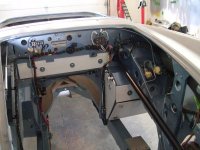
In planning stages now, but will report back with pics on the project later. Thanks, GONZO
AHY-080.gif
 
Last edited:
Woodruff keys are in the Dorman small parts bins at OSH. for the dimensions, suggest measuring the width of the slot and depth of the groove in the pulley. Shouldn't be too hard to arrive at dimensions.

Make sure you have the Dynamator checked before installing. I have one with fried stator windings due to a voltage regulator that died after 20 miles of driving. Make sure your battery is charged up before operation.
 
Hello Gonzo, Dave Russell's entries are excellent technical direction. I just wanted to add some points and give you some pics for ideas. I used a Chevrolet AC Delco Alternator for a couple of reasons. 1 is that I am very familiar with it. 2 I is very good quality and long lasting and 3 if it does fail replacements are at any auto store. Another point would be that you don't have to change over the pulley, etc. I bought my mounting kit from Allen Hendrix at Hendrix wire wheel. Fan belt is available at any store. Allen is a fabulous help. Steve mentioned that you should make sure that your battery is charged before you fire this thing up. There is good reason for that and in the pics you will see that I have installed a red #10 wire from my alternator "BAT" terminal to the large battery cable at the starter solenoid. This gives a very good High Amperage pathway back to the battery. If you battery is low like maybe upon first use after a winter hibernation, the alternator will try to put out its max current. The wires in the Healey wiring harness are too small for this. The #10 wire from the alternator to the battery terminal at the solenoid, even though technically rated for 30 amps and not the full rating of the alternator will substantially reduce the possibility of over heating any wires.
I chose to not screw around with faking a regulator. I installed a terminal strip where the regulator was. You could put a backing plate behind the terminal strip and screw the regulator cover to that to simulate that there is a regulator there. If you look closely at the pic of the engine compartment you can make out the colours and how they are hooked up. You will also see the #10 red wire running up the right side support brace and into the firewall then it comes back out and goes down to the solenoid. It goes into the passenger compartment because it goes to an amp meter but you could skip that part and just run it from the alternator to the solenoid. I also attached a pic of the circuit that I drew of how it works. Vette.
 

Attachments

  • img182.jpg
    img182.jpg
    29.8 KB · Views: 134
  • DSCF1989.jpg
    DSCF1989.jpg
    64.5 KB · Views: 145
  • DSCF2505.jpg
    DSCF2505.jpg
    77.8 KB · Views: 139
These ideas and suggestions are extremely helpful and it makes my decision about converting a lot easier. Precautions against overcharging is particularly appreciated as I have read a couple of conversions "double-up wiring e.g 2 x 12G" or even better, augment with a 10G as Vette describes. Installation of an period Jaeger ammeter is also planned; gauge sweep is just 30 AMPs but it still may work for my purposes.

OSH fixture bins are my go to place for small parts and I plan to raid it for miscellaneous conversion parts. Thanks for all the advise and a reminder from the late Dave Russell that there are always creative and often simple solutions. GONZO
 
Gonzo, if you are planning to put an amp meter in then I would like to make a few more points. Wiring in the amp meter as in my drawing will not allow the amp meter to work as planned. I did it incorrectly in the beginning and have never corrected it because just haven't gotten around to it. As it is in my circuit drawing the amp meter will show charge but will not show a discharge. That is because where it is located in the circuit it sees what the alternator is putting out but it is not where it will sense any draining currents from the different loads of the car. I have a corrected drawing somewhere and i will try to find it momentarily. Also you will notice in the drawing that I have installed a shunting resistance around the meter. This is to create two parallel paths for the current so that the meter only sees some of the totally charging current. I was more interested in whether it was charging or not and not in exactly how much current was moving. Also the shunt will protect the meters 30 amp winding. If you size the shunt correctly you can dictate exactly how much amperage will go thru the meter. At this my shunt is nothing more than a piece of #14 wire and I hardly see the meter needle move.
If you want to have the meter work for charge and discharge you can wire it into the circuit as shows in my next picture. Or you can look up the wiring schmatic for an early Jaguar such as an E-type or an XK. They had amp meters installed with similar electrical layouts to the Healey. I have a voltmeter installed as well and in reality like many will tell you, you live my the voltmeter, to 'ell with the amps. ..... ok found the drawing. In the new drawing you will see that the brown wire from the terminal strip (old regulator location) is now attached to the alternator side of the amp meter. With it like this, if the Alternator stop charging the battery, and the devices from the car start to pull from the battery instead of the output of the alternator, then the meter will show a discharge. When the alternator is putting out and charging, it supplies voltage and amps to the battery and the devices of the car via the brown wire.
 

Attachments

  • img263.jpg
    img263.jpg
    42 KB · Views: 119
I used to have an ammeter and voltmeter, but removed the ammeter for three reasons:
- I needed room for more switches,
- Having an ammeter means more high-current wires running under the dash, which increases the possibility of a high-current short, and
- I can get a better indication that the battery is being charged with a voltmeter.
 
Back
Top