-
 Hi Guest!
You can help ensure that British Car Forum (BCF) continues to provide a great place to engage in the British car hobby! If you find BCF a beneficial community, please consider supporting our efforts with a subscription.
There are some perks with a member upgrade!**Upgrade Now**
(PS: Subscribers don't see this gawd-aweful banner

Tips
- We have a special forum called "Member Articles" where you can submit actual articles for consideration for publication. Learn More
- Don't have an Avatar? If not, your avatar will default to the 1st character in your username. Go into "Account Details" to change your Avatar.
- Some basic forum navigation info: click
 Hey - did you know if you click on the title of a thread it will take you to the first unread post since you last visited that thread?
- Hey Guest - Is your British Car Club in our Clubs database? If not, send me a PM - Basil

- Looking for a local club? Click the "Clubs" tab above and browse hundreds of clubs world-wide.
- Add Android or iPhone APP: click
- Did you know - any picture or video you add in your posts in any marque-specific forum will also get added to the Media Gallery automatically.
- A few more tips about posting and replying: click
- Hey there Guest - be sure to keep your profile page up to date with interesting info about yourself: learn more
- More tips and tricks on Posting and Replying: click
 but were afraid to ask:
  STOP!! Never post your email address in open forums. Bots can "harvest" your email! If you must share your email use a Private Message or use the
  smilie in place of the real @
- Want to mention another member in a post & get their attention? WATCH THIS

- So, you created a "Group" here at BCF and would like to invite other members to join? Watch this!
- Hey Guest - A post a day keeps Basil from visiting you in the small hours and putting a bat up your nightdress!
- Hey Guest - do you know of an upcoming British car event?
 Pretty Please - add it to our Events forum(s) and add to the calendar! >> Here's How <<
- Hey Guest - you be stylin' Change the look and feel of the forum to fit your taste. Check it out
- If you run across an inappropriate post, for example a post that breaks our rules or looks like it might be spam, you can report the post to the moderators: Learn More
- If you would like to try some different "looks" or styles for the site, scroll to the very bottom, on the left and click the Style Selector.
You are using an out of date browser. It may not display this or other websites correctly.
You should upgrade or use an alternative browser.
You should upgrade or use an alternative browser.
fuel guage for Jack
- Thread starter bugimike
- Start date
msoylemez
Jedi Trainee
Offline
Mike, I just asked the question elsewhere, but I will ask you here since you provided pics and you have been helpful (sorry if I'm taking advantage here...hehe):
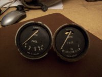
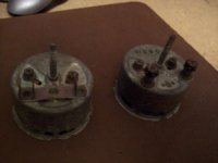
The back of my gauge looks like the gauge on the left side in the pic. It's got the 3 square posts, the 2 nuts that can slide up and down for what reason I have no idea and then finally the long pin/post which, along with the u-clamp looking item (not seen in picture) secure the gauge once its in the dashboard.
So I have 3 wires on my harness that appear to run to the fuel gauge. One is black, so that's ground, and I am attaching that to the long pin/post once the u-bracket clamp is in place.
Where do the other two non-black wires go to? The wires have eye/round-terminal ends...
Thanks!
Mustafa
jlaird
Great Pumpkin
Offline
Ha, the one with the tabs has a Bugeye face but the tabs are for a later car when they changed to them, maybe a MK 1 midget.
Either or Mike, I have a face so I can replace the strange one even. However, I would prefer the one on the left if it works.
Just do not ever mess with the short nuts, they are an adjustment system and ring, glass, face and the blue plastic thing for the light are removeable with out messing with them.
OP
bugimike
Yoda
Offline
Jack those two nuts that can slide up and down are actually adjustments to set the "full" and "empty" setting sweep of the needle!! I imagine you could bench test it with a sending unit. One of the nuts is marked "T" and the other "B" ...Top and Bottom of the sender range!!
You have the one on the left on the way, and as far as I know, they both work. If it doesn't, let me know and I will send you the other and hopefully that one will. I'm sure you know how it is with parts that have sat in a drawer for who-knows-how-long!
Mustafa, the two wires go to the terminals <u>above</u> the "sliding" nuts (which you really do not want to touch as they adjust the full and empty readings!). You are correct, the black goes to the center post and is the ground, the others as I said attach to each of the spade (square) terminals. If your wiring has eyes, you can switch them to female spades. You can use the crimp-on kind, though I prefer to solder my connections.
PS Green goes to the side marked "B" and green/black to side marked "T"
msoylemez
Jedi Trainee
Offline
Ok, so I am assuming one wire goes to the right spade, and the other goes to the left and the spade in the middle is left alone?
Why put it there then?
BTW, I have, of course, completely messed around with the sliding screws as I originally thought this is where the wires went to....sweet.
Why put it there then?
BTW, I have, of course, completely messed around with the sliding screws as I originally thought this is where the wires went to....sweet.
OP
bugimike
Yoda
Offline
Good question...sorry, I have no answer. Maybe something else could be wired in series??
To reset those screws you shouldn't have touched, set them approximately in the middle of the slots and start there. You will either have to fill and drain your tank, or take your time and watch the guage as you use fuel. With the tank empty, when the ignition is on, the needle will move from park (against the pin on the far left)to "E". if it does not, nut on the back marked "B" needs adjusting until the needle is on "E". The same must be done with the tank full to get the needle to "F" by adjusting "T".
To reset those screws you shouldn't have touched, set them approximately in the middle of the slots and start there. You will either have to fill and drain your tank, or take your time and watch the guage as you use fuel. With the tank empty, when the ignition is on, the needle will move from park (against the pin on the far left)to "E". if it does not, nut on the back marked "B" needs adjusting until the needle is on "E". The same must be done with the tank full to get the needle to "F" by adjusting "T".
ncbugeye
Jedi Warrior
Offline
I would venture to say that anything with spade terminals is NOT original late 1950s or early 1960s Lucas equipment. Spade terminals came later and may have been fitted as original equipment to late 1960s and 1970s era vehicles, but I do not think to Bugeyes.
For some reason when they did start to appear, I think in the mid-1960s, they were obscurely and confusingly referred to as "Lucar" connectors.
ncbugeye's fuel gauge has BA nuts and washers on studs, and the face of the gauge is exactly like the left-hand picture above.
For some reason when they did start to appear, I think in the mid-1960s, they were obscurely and confusingly referred to as "Lucar" connectors.
ncbugeye's fuel gauge has BA nuts and washers on studs, and the face of the gauge is exactly like the left-hand picture above.
OP
bugimike
Yoda
Offline
Well, Drew, the left hand top picture (and rt. hand bottom) must be an original BE unit (and is the one I sent to Jack)and the one on the right must be a newer one. I did not mess with either, they were just in my collection of "stuff". The one in my BE is much newer than either as the face is quite different (it has a little "window" for the needle display. If only this "stuff" could talk eh? I am not a real stickler for originality like that, though if something is "correct" I will try to maintain it as such. So long as I get an accurate reading of how much fuel I have, that's what is important! I am hoping the one I sent to Jack is in good working order now since it is the oldest in my collection!!
